Description:
Intensity of Remote Signalling Alarm Contact
Failure indication and centralized remote signalling alarm dry contacts;
High discharge capacity and low residual voltage;
Over-temperature protection;
IP20, UL94 V0
| Model Number | SUP1 |
| SPD according IEC 61643-1 | Class II |
| SPD according EN 61643-11 | Type 2 |
| Operating Temperature Range | -40ºC~+80ºC |
| Relative Humidity | ≤95%(25ºC) |
| Atmospheric Pressure | 86~106kPa |
| Working Frequency | 50/60Hz |
| Rated Working Voltage Uo | 230V/400V~ |
| Max Continuous Operating Voltage Uc(L-N) | 275V/320V/385V/420V ~ |
| Mode of protection | L-N/N-PE |
| Nominal Discharge Current In(8/20μs)(L-N) | 20kA |
| Max Discharge Current Imax (8/20μs) (L-N) | 40kA |
| Voltage Protection Level Up(L-N) | ≤1.2kV |
| Max. mains-side Overcurrent Protection | 80A(gL/gG) |
| Cross sectional area for wiring terminal connected to conductor | Stranded:4~25mm² Solid Wire: 4~35mm² |
| Max. Cross-sectional Area For Remote Signaling Interface | 1.5mm² |
| Torque: wiring terminal/remote signaling interface | 2.5Nm |
| Enclosure material | PBTV-0 |
| Degree of protection(IP code) | IP20 |
| Mounting | DIN35mm rails |
Solar DC SPD
The SUP series Surge Protection are designed to protect against lightning surge voltages in photovoltaic power supply networks.
These units must be installed in parallel on the DC networks to be protected and provide common and differential modes protection. The SUP series is available for the main operating voltages in photovoltaic: 1000 Vdc.
The use of SUP series Surge Protection is recommended at both ends of the DC power supply line (solar panel side and inverter/converter side),
Especially if the line routing is external and long. The electrical diagram of the SUN-S40 series is based on high energy PV equipped with specific thermal disconnectors and related failure indicators.
The SUP series is made with plug-in modules to allow a fast and easy maintenance in case of failure (disconnection from the DC network).
| SUP2-PV series surge protector | SUP4-PV | ||
| PV DC specific (LEC 6614-1/EN 61643-11) | |||
| Pole | 2 pole | 3 pole | |
| Electrical Parameter | |||
| Classifical test | II | II | |
| Uoc max (V DC) | 500 | 900 | |
| Uc (V DC) | 500 | 1000 | |
| In(8/20)us (KA) | 20 | 20 | |
| Imax(8/20)us (KA) | 40 | 40 | |
| Up (KV) | 2.0 | 3.8 | |
| Remote control and indication | |||
| Indication window | |||
| Plug-in module | |||
| Remote signal contact | |||
| Remote signal contact | Max working volt | 250V AC/30V DC | 250V AC/30V DC |
| Max working amp 1A (250V/AC) | 1A (250V/AC) | 1A (250V/AC) | |
| 1A (30V DC) | 1A (30V DC) | 1A (30V DC) | |
| Wiring & installation | |||
| Wiring capacity(mm2) | Hard wire | 4-25 | 4-25 |
|
 |
Flexible wire | 4-16 | 4-16 |
| Stripping length | 10 | 10 | |
| Terminal screwa | M5 | M5 | |
| Torque(Nm) | Main ciruit | 3.5 | 3.5 |
| Remote signal contact | 0.25 | 0.25 | |
| Protection class | All profile | IP40 | IP40 |
| Connection port | IP20 | IP20 | |
| Installation environment | No obvious shock and vibration | ||
| Altitude(m) | ≤ 2000 | ≤ 2000 | |
| Working temperature | -3.0--+70 | -3.0--+70 | |
| Relative humidity | 30%-90% | 30%-90% | |
| How to install | Install with H35-7.5/DIN35 stell mounting rail | ||
| Size(mm) (W*H*L) | W | 36 | 54 |
| H | 90 | 90 | |
| L | 67.6 | 67.6 | |
| Weight (KG) | 0.25 | 0.38 | |
| Nominal PV system volt | 600V | 100V | 1200V |
| MCOV(UCPV) | 700V DC | 1170V DC | 1200V DC |
| Max system discharge Current (8/20us) (Imax) | 40KA | 40KA | 30KA |
| Volt protection leve (UP) | ≤ 2.5KV | ≤ 4.0KV | ≤ 4.5KV |
| Volt protection Level at 5KA (UP) | ≤ 2.0KV | ≤ 3.5KV | ≤ 4.0KV |
| Integrate fuse breaking capacity/interrupting rating | 30KA/1000V DC | 30KA/1000V DC | 30KA/1200V DC |
| Technology | Short-circuit interruption (SCI) overcurrent protection | ||
| Operating temperature range | -40 to +80 | ||
| Nominal discharge current | 12.5KA | ||
| Response time (ta) | <25ns | ||
| Operating state/fault indication | Green (good) / Red (replace) | ||
| Mounting | 35mm DIN Rail per EN 60715 | ||
| Degree protection | IP20 | ||
| capacity | 3 modules DIN 43880 | ||
phone:008615067704943
Gin Poles
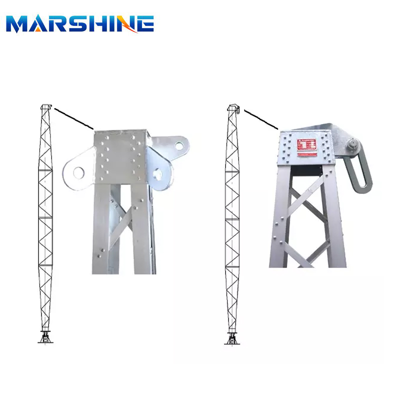
The main structural forms of gin poles are single holding pole, herringbone holding pole, rocker arm holding pole, flat arm holding pole and combined holding pole. Hard aluminium alloy with yield strength not less than 2A12 (T4 state) is used for main and auxiliary materials of aluminium holding rod, and alloy steel with yield strength not less than Q345B is used for main and auxiliary materials of steel holding rod.
During used for transmission and distribution line engineering, sling tower material, positioning pulley set use. Adopt single-arm style, free from direction restriction, use convenience. The main material adopts right angle aluminum titanium alloy section, rivet joint makes, portable and durable.

Gin Poles,Inner-Suspended Tubular Gin Pole,Inner-Suspended Lattice Gin Pole,Aluminum Alloy Lattice Single Gin Pole,Small Gin Pole,Steel Inner-Suspended Gin Pole
MARSHINE , https://www.puller-tensioner.com