Although 12V lead-acid batteries are still the mainstream of automotive power supplies, some new applications require higher voltages, such as trunk audio power amplifiers and window defrosters. To meet the requirements of these high voltage applications, a new generation of AEC-Q100 certified synchronous boost controllers has emerged on the market. This controller is designed to boost the 12V battery voltage, withstand spikes up to 60V, and with the high reliability required by new models.
This article describes a pair of easy-to-use 2-phase 55V synchronous boost controllers that produce 24V, 36V or 48V rails in automotive environments with only 12V supplies. We'll look at some of the key features of their integration, including comprehensive protection features that help optimize the solution to reduce costs and increase efficiency, security, and reliability. We will also discuss an integrated PMBus interface that provides advanced control, telemetry, and diagnostic capabilities and simplifies the task of achieving ISO 26262 compliance.
Raise the 12V battery voltage
One of the challenges that system design engineers have always faced is how to achieve greater power efficiency while minimizing board space. The ISL78227 and ISL78229 55V Synchronous Boost Controllers solve this problem by integrating an advanced FET driver that adaptively adjusts the number of switchings to prevent cross-conducting (TI) when simplifying power stage design. The 2-phase configuration of these two controllers reduces ripple current, allowing for smaller input and output capacitors, which helps reduce board footprint. Two controllers can be used in parallel to increase the number of phases to four to support higher power output levels.
The ISL78227 and ISL78229 feature a PMBus interface that supports a wide operating frequency range of 50kHz - 1.1MHz and can be configured to optimize operating frequencies by using smaller external components to help increase efficiency or minimize board space. They include many features designed to maximize efficiency, which is important because the peak output current of a 12V battery will exceed 30A at 400W load.
Synchronous FET for output rectification
Since most buck converters have low output voltages, FETs are often used in buck converters instead of diodes for output rectification. In this configuration, a large percentage of the power loss in generating the output voltage comes from the voltage drop across the rectifying element. Using a synchronous FET that can be turned on and off at the appropriate time instead of an output rectifier diode can greatly increase efficiency. This is because FET losses typically only account for a small fraction of the rectifier diode losses. In a buck converter, the reference voltage of the synchronous FET is a ground voltage, so the drive circuit is relatively simple.
Synchronous FETs offer a number of benefits to the boost configuration. In boost converter applications, the output voltage is typically several times the input voltage, so the power loss produced by the output rectifier components is a small percentage of the total output power. Boost converters benefit from increased efficiency of synchronous FETs, while synchronous FETs provide bidirectional current, which supports continuous mode operation (even under light load conditions) – an important advantage for applications requiring low electromagnetic interference (EMI). Bidirectional current flow is also an important capability to achieve efficient envelope tracking, which we will discuss below. In addition, the use of a synchronous FET does not preclude operation in discontinuous mode. The boost controller is capable of detecting negative current flow and has the option of disabling the synchronous FET to simulate the function of the synchronous rectifier diode.
Improve light load efficiency through diode simulation
Audio signals often change dramatically in a very short period of time. At this point the amplifier may require a high power burst and a very low power burst may be required in the next moment. It may even be muted during an audio session. When this happens, the power consumption of the amplifier will drop significantly, because of this, the power demand of the boost regulator will also drop to a lower value. In fact, under light load conditions, the boost inductor current can be reduced to zero. When this happens, the output voltage (boost voltage) of the inductor is higher than the input voltage (battery voltage). If the sync FET remains on during this condition, the current will begin to flow back through the inductor and get the charge from the output capacitor.
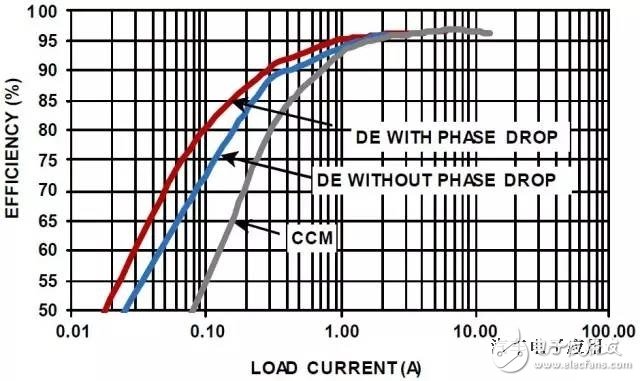
Figure 1. Efficiency versus load comparison, 2-phase boost configuration, three operating modes, fSW = 200kHz,
VIN=12V, VOUT=36V, TA=+25°C
These 55V boost controllers include an optional circuit to avoid this reverse conduction loss by having the synchronous FET simulate the current blocking behavior of a real diode. This smart diode operation, called Diode Emulation Mode (DEM), acts to turn off the synchronous FET when it senses that the inductor current begins to flow in the wrong direction. If the controller enters diode emulation mode and the load is still decreasing, the controller will enter a pulse omitting mode to reduce the number of switching cycles, thereby increasing its efficiency at very light loads on the output.
Although DEM can improve efficiency under light load conditions, it also presents some electromagnetic interference challenges due to changing switching characteristics. To avoid electromagnetic interference problems, it is often desirable to maintain continuous conduction mode (CCM) operation. Of course, this will sacrifice the efficiency gain brought by diode simulation, as shown in Figure 1. However, in applications such as audio amplifiers, an alternative to achieving light load efficiency gains is to have the amplifier power supply use envelope tracking to track input requirements.
Forced PWM mode
Many power system applications require that the converter's switching frequency be kept constant to minimize the possibility of interference. Due to this requirement, the ISL78227 and ISL78229 can also operate in PWM mode (no pulse omitted). However, in forced PWM mode, reverse current may flow, such as entering the pre-biased output state at startup, or when the output voltage rises above the expected voltage. In a typical system, there is no way to limit the reverse current, which can damage the sync FET. The ISL78227 and ISL78229 solve this problem by providing reverse current limiting. Limiting negative current reduces output voltage transients and increases system reliability. As a result, the design engineer can configure the boost controller to force the PWM mode without worrying about the reverse current being out of control.
Improve light load efficiency with Phase Shedding
The ISL78227/29 synchronous boost controller supports 2-phase boost operation, and we can connect the two devices for four-phase operation (see Figure 2). Under heavy load conditions, the main system losses are due to conduction losses and switching losses, but under light load conditions, switching losses begin to become a major loss factor. To increase efficiency, both controllers can be configured to monitor system current levels. If the load drops below a certain threshold, the controller subtracts one phase, which reduces switching losses under light load conditions. The phase shielding process is completed in 15 switching cycles to prevent load transients. If the load subsequently increases above the threshold, then immediately add a phase to manage the increased load.
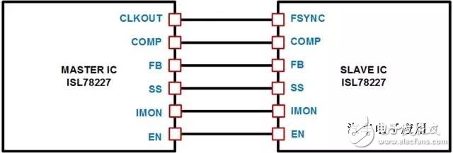
Figure 2. Supporting 4-phase operation by connecting two devices to meet the requirements of higher power applications
Reference voltage control and audio envelope trackingThe boost controller output voltage can be adjusted using the 1.6V on-chip reference voltage or it can be adjusted to the external tracking voltage used to drive the control loop. The ISL78227 and ISL78229 controllers are unique in that the external signal used to drive the tracking function can be configured as an analog voltage or PWM signal. These TRACK functions dynamically support changes in the output boost voltage. These controllers include negative current limiting and protection, which is useful when envelope tracking flows from higher voltages to lower voltages.
The task of outputting the boost voltage is inherently a tracking control signal, but when changing from a higher voltage to a lower voltage, the output capacitor must be discharged to cause the voltage to drop. If the load itself does not consume enough current, the synchronous FET can help discharge the output capacitor without worrying about FET damage due to excessive current. This is because both controllers include negative current limiting and protection circuitry for these conditions.
For audio applications where the supply voltage varies rapidly over a wide range, it is useful to be able to support envelope tracking without worrying about excessive reverse current. In audio applications, the TRACK signal can be used to control the raised output voltage so that it can track changes in the signal amplitude of the audio amplifier. This keeps the supply voltage steady and prevents short-term pulse wave interference during load changes, preventing popping from the audio power amplifier.
In automotive audio power amplifier applications, it is common to raise the 12V battery voltage. These boost controllers can boost the battery voltage to 48V or any desired voltage to support the power level of the audio power amplifier. Audio amplifier power is very common in the 100-800W range. Multi-channel systems for some premium audio systems may include 30-40W amplifiers and a higher power amplifier for driving subwoofers.
In analog audio amplifiers, efficiency can be improved if the supply voltage is only large enough to support the audio signal. The efficiency improvement of digital audio amplifiers depends on the digital amplifier architecture.
PMBus controlThe ISL78229 boost controller shown in Figure 3 includes a PMBus interface that helps the design engineer's system achieve ISO 26262 compliance and achieve Automotive Safety Integrity Level (ASIL) requirements. The PMBus interface is useful in systems that require real-time telemetry, reporting errors to the microcontroller, and system control. It provides a way to remotely enable or disable the boost controller and to monitor and report variables such as input voltage, input current, and output voltage. In addition, the boost controller includes a pin to support the measurement of an external negative temperature coefficient (NTC) resistor to monitor temperature. It then digitizes the signal and also reports the readings via PMBus. An overtemperature fault limit for external temperature monitoring can also be set.
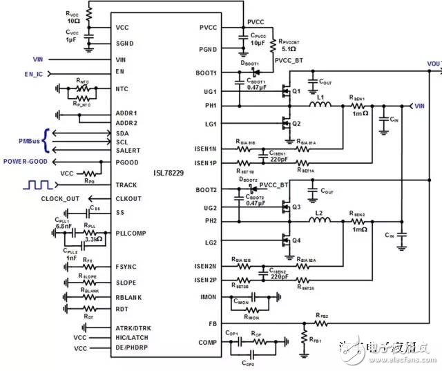
Figure 3. Typical application of ISL78229 with PMBus control
The boost controller also features fault reporting such as input overvoltage, output overvoltage or output undervoltage, overcurrent, and overtemperature faults. Each function can be monitored via PMBus. Adding a PMBus interface helps avoid the need for dedicated telemetry circuits.
in conclusionThe ISL78227/29 multiphase 55V synchronous boost controller offers many features to meet many different power system requirements. These features alone may not be trivial, but when combined, the overall effect far exceeds the sum of their respective roles. Voltage quality modules for start-stop systems, trunk audio amplifiers, and window defrosters are just a few of the high-voltage applications that require a stable boost controller solution.
About the author
Jerome Johnston is an applications engineer with Intersil's Central ApplicaTIons team. He has more than 30 years of experience in analog system design and application and is the owner of 13 US patents. Jerome holds a bachelor's degree in electrical engineering from the University of Nebraska.
SCOTECH offers a full range of special transformers for both AC and DC voltages. Including AC/DC Furnace Transformer , Rectifier Transformer, Grounding Transformer, K Rated Transformer, traction transformer, and other special application transformers, with years of experience, lots references from different applications and a global operation footprint, SCOTECH is experienced to make the customer's special application transformer.
By using the best quality of materials for the transformer core and windings, a reduction of losses has been achieved. For the end-user this means that with lower losses, more economy, and makes the payback time of the investment shorter. The lifetime of the transformer is also extended.
Why SCOTECH
Long history- Focus on transformer manufacturing since 1934.
Technical support – 134 engineers stand by for you 24/7.
Manufacturing-advanced production and testing equipment, strict QA system.
Perfect service-The complete customer service package (from quotation to energization)
Special Transformer,Earthing Transformer,Traction Transformer,Phase Shifting Transformer
Jiangshan Scotech Electrical Co.,Ltd , https://www.scotech.com