The waveguide crack array antenna can easily control the amplitude distribution and phase distribution on the aperture surface. The aperture surface has high utilization efficiency, small volume, low profile and light weight, and has been widely used in radar and microwave communication systems. However, more and more requirements require the antenna to conform to the platform carrier, which puts higher requirements on the crack array antenna. In the cylindrical conformal array, it is necessary to compensate for the nonlinear phase difference caused by the difference of the path from the radiation source on the cylindrical surface to the flat surface of the design, such as a cylinder with a diameter of 30λ and a plane with an arc width of about 10λ. The maximum difference between the path difference caused by the equivalent flat surface is 260°. It is indicated by calculation that if it is not compensated, the main lobe of the antenna will crack, so it must be designed to compensate the phase difference.
2 antenna designA. Indicator requirements
Frequency: f0 ± 50MHz;
Antenna diameter: about
![]()
The antenna needs to conform to a cylinder with a diameter of f = 30λ
Gain: 35dB;
Beam width:
Q surface: 5.0°;
P face: 0.6°;
Sidelobe level:
Q face: -13dB,
P surface: -18dB;
B. Electrical performance design
The crack array antenna is composed of a radiation layer, a coupling layer and a feeding system. The coupling layer and the feeding layer are in the same layer to meet the thickness requirement of the antenna, and the coupling layer is a circular curved waveguide, which is fanned through the coupling hole on the common wall. Waveguide feed, as shown in Figure 1.

Figure 1 Side view of the cylindrical conformal array
(a) P-side electrical performance design
Each line source has a total of 136 array elements, and its aperture distribution is designed according to the Taylor distribution of the sidelobe level -22dB. Figure 2 is the amplitude distribution of the aperture. According to the excitation given in Figure 2, the corresponding expected direction is shown in Figure 3. The beam has a half power width of 0.59° and a sidelobe level of -22 dB.
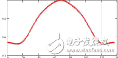
Figure 2 Amplitude distribution of the line array
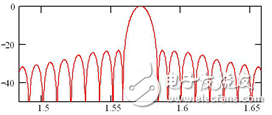
Figure 3 antenna line array -22dB side-lobe Taylor distribution pattern
In the present antenna array, for the consideration of the operating frequency bandwidth of the array, each line source is divided into four equal-length short-line sources, and a short-line source of each part and a sub-array composed of 12 other short-line sources arranged in parallel with each other Then, they are combined into one by a one-to-four waveguide power division network. Since the array is amplitude-weighted in the axial direction, the radiated power of each sub-array is not the same. In order to satisfy the amplitude distribution, the power division ratios of the four outlets of the sub-array are 0.144, 0.356, 0.356, and 0.144 (or -8.416 dB, -4.464 dB, -4.464 dB, and -8.416 dB), respectively.
(b) Q-face electrical performance design
The Q-plane electrical performance design is the design focus of the conformal array, that is, the coupled array design is the focus of the antenna design, and the spatial phase difference is compensated by the design of the coupled array. The position and coupling strength of the feed waveguide coupling slot determines the aperture distribution of the line source arranged in a circular arc on the Q plane. The phase difference caused by the fact that the Q-plane lines are not in the same plane position in space is shown in Fig. 4.
Such phase difference must be compensated, otherwise the surface beam will appear concave. If we assume that the amplitude of the area array in the arc direction is distributed in a uniform manner, the direction diagram is shown in Figure 5.
The pattern after the spatial phase difference compensation is shown in Fig. 6. It can be seen from the figure that the Q-plane pattern after phase compensation by the feed waveguide is basically consistent with the original expected pattern. That is, the main lobe width of the pattern is 5.1°, and the sidelobe level is about -13.3dB, which satisfies the requirements for beam width and sidelobe level.
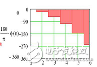
Figure 4 Spatial phase difference
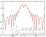
Figure 5 Q-plane pattern without phase compensation
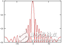
Figure 6 Q-plane pattern after phase compensation
Phase compensation scheme design
In the design of cylindrical conformal arrays, a design method of phase compensation is given in [4]. The coupled waveguide adopts a traveling wave array, and the upper and lower offsets of the slits in the wide waveguide cause π phase shift and offset. The size and the inclination of the seam simultaneously control the phase shift and amplitude. In the design, the phase of the radiant slit to the phase of the imaginary flat surface and the phase of each radiating waveguide in the coupled waveguide must be appropriately selected to compensate the phase difference by the position of the oblique slit when the residual phase difference is small. The design is more complicated and cumbersome, and it is found in the simulation verification that the compensation method is inconsistent to the phase caused by the two ports of the radiation waveguide.
The coupled waveguide adopts a wide-edge open-slit static standing wave array, and the angles of the oblique slits are equal, satisfying the Q-plane equal-amplitude distribution, the adjacent angles are positive and negative, and the spacing is
![]()
, satisfying the in-phase distribution, and feeding the middle to the radiation waveguide. A longitudinal slit is formed in the radiation waveguide, and a standing wave array is used to control the required phase by the distance of the longitudinal slit from the coupling slit. The amplitude distribution of the P plane is realized by adding an inductive diaphragm to the radiation waveguide near the slit.
By controlling the distance of the radiation slot to the coupling slot, the phase of the control radiation slot can be controlled, and the relationship between the required phase and distance satisfies the equation (7). d is the required spacing, and the relationship between the required phase and the wavelength of the waveguide in the radiating waveguide is
![]()
In order to verify the correctness of the theory, the simulation is carried out by constructing the model shown in Fig. 7. The spacing of each radiation slot relative to the coupling gap is
![]()
, n take ±1, ±2, ±3, parametric scan of d, take a seam on the left and right sides of the feed seam to see the near-field phase, you can see the relationship between d and phase, consider the general take the intermediate seam . The simulation results are shown in Figure 8.
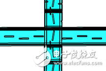
Figure 7 Modeling
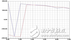
Figure 8 Relationship between phase and spacing
The simulation results are consistent with the theoretical calculation results, which verifies the correctness of the feed phase scheme.
3 large array simulationA. Features of CST Microwave Studio®
The antenna aperture of the cylindrical crack array reaches
![]()
In addition, it has a conformal structure, and the cylindrical slits, inductive diaphragms and the like are very fine, which makes the full-wave simulation analysis very complicated.
The 3D electromagnetic field simulation software CST Microwave Studio® uses a finite integration algorithm that can quickly handle time domain wideband and large size problems. After using the Ideal Boundary Fit® (PBA) technique in the finite integral algorithm, CST Microwave Studio® not only maintains a structured Cartesian grid, but the classical FDTD algorithm is limited to Staircase Mesh. All the advantages, and can accurately model the curve structure, achieving a double guarantee of accuracy and speed. CST Microwave Studio® has the best 3D modeling interface in the industry, which can quickly and accurately create and modify 3D geometric models. Its time domain solver can calculate the full-band parameter characteristics under one excitation simulation, so it is very suitable for this. Modeling and simulation of the problem.
B. Modeling
Using the symmetry of the model, only half of the structure can be created during modeling, and the simulation task can be completed with symmetry.
The model consists of 12 radiating waveguides and two feeding waveguides. There are choke slots between the radiating waveguides, and each radiating waveguide has 68 or so radiating slits. The antenna array is divided into two sub-arrays, I and II, and two feed waveguides are respectively located in the two sub-arrays. Each of the feed waveguides has twelve feed slots corresponding to the radiating waveguide, and the metal diaphragm corresponds to the feed gap.
Not only are there a large number of radiating gaps, but the gaps in each radiating waveguide are not the same, and symmetry modeling cannot be directly used. If you model each gap separately, there is no doubt that the workload is huge. Here is a semi-automatic modeling method based on CST VBA macro commands to simplify this cumbersome process.
The final simulation model is shown in Fig. 9. The feed waveguide port of the I sub-array is set to port 1, and the II sub-array feed waveguide port is set to port 2. The amplitude ratio of Port 1 and Port 2 is 0.637:1.
C. Simulation results
Using the time domain solver of the CST microwave studio, the total number of meshes simulated by the entire crack array antenna reaches 142, 156, 080, and fine structures such as the crack array and the feed waveguide metal diaphragm are finely resolved. Figure 10 and Figure 11 show the P-plane and Q-plane directions of the antenna at the center frequency f0.
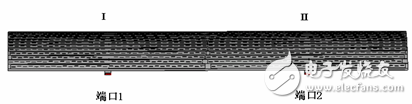
Figure 9 Waveguide Port Settings
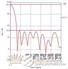
Figure 10 P-plane gain pattern
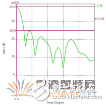
Figure 11 Q-plane gain pattern
It can be seen that the antenna gain reaches 38.4dB, the P-plane sidelobe level: -22.1dB, the beam width is 0.6°, the Q-plane sidelobe level is -13.3dB, and the beam width is 5.6°. The simulation results and theoretical design have achieved good agreement.
4 ConclusionThe antenna adopts a new phase control technology to compensate the phase difference caused by the unequal length of the cylindrical slot array, and realizes the Q-face conformal design. The correctness of the scheme is verified by CST commercial simulation software simulation. Sexuality provides a new solution for the design of conformal array antennas. The simulation results show that the antenna meets the required index requirements. The main technical indicators are: P-face half-power beam width: 0.6°, P-plane sidelobe level: -22dB, Q-face half-power beam width: 5°~6 °, Q side sidelobe level: -12dB or so, the gain is greater than 37.7dB, which is in good agreement with the theoretical design.
Fiber Pen Nib,Passive Capacitive Stylus Pen,Rubber Tip Stylus Pen,Microsoft Stylus Pen
Shenzhen Ruidian Technology CO., Ltd , https://www.szwisonen.com