I. Introduction
The constant pressure public address system is currently the mainstream of public broadcasting projects. Although some large-scale public broadcasting systems use network transmission, most of the terminals in the network and the broadcasting service area to which the system is controlled by the system are still using constant-voltage power line transmission.
With the development of the economy, there are more and more large-scale public broadcasting systems, and the coverage scale is in kilometers. For example: Tiananmen Square: 880m long from north to south, 500m (44h) from east to west; Guangzhou Zoo: 400m×1100m (about 43 hectares); 300 hectares of South China Botanical Garden; Zhejiang University: 136 hectares; Beijing Railway Station: length of each platform: about 600m Beijing Olympic Park: 680 hectares of forest park, 405 hectares of stadium center... Even indoors, some large venues such as airports, convention centers, technology exhibition halls, and large supermarkets have very large scales. Therefore, the transmission line has become a problem that cannot be ignored, and its engineering quantity and investment amount are often “overwhelming†and become the main body of the project.
There are two aspects to the engineering problem of constant pressure public broadcasting transmission lines. One is the route of the line and its topology; the other is the entity of the line, including transmission voltage, line section and line loss. This article is only for the latter.
Second, the transmission line model of constant pressure public broadcasting
Although many transmission lines for constant-pressure public broadcasting may be long, they cannot be considered as "long-term". Because the audio signal is transmitted, its theoretical frequency band is 20Hz~20kHz (the actual transmission frequency in engineering is below 12.5kHz). With its highest component, 20 kHz, the shortest wavelength of the transmitted signal is:
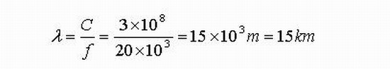
Where λ is the wavelength (m), C is the speed of light (m/s), and f is the frequency (Hz).
The visible wavelength is still much longer than the actual line. Therefore, the line can still be described by the lumped parameters, and the distributed reactance is also negligible. The model is shown in Figure 1.
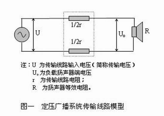
For engineering, everyone cares about how to choose a transmission line, especially how to determine the cross section of the transmission line. There is no doubt that the line section is related to factors such as transmission voltage, load, and allowable attenuation.
Below, we use the line section as the dependent variable to build the calculation model.
1, the equivalent resistance of constant pressure broadcast speakers
Constant-voltage broadcast loudspeakers usually have two parameters: the rated operating voltage U (which must be compatible with the line transmission voltage, hence the transmission voltage) and the rated power P. Its equivalent resistance is:

Where U is the rated operating voltage (V) of the speaker and P is the rated power (W) of the speaker.
2, the gain and attenuation of the transmission line
According to the definition of gain:
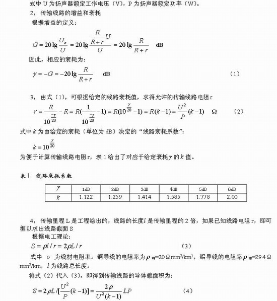
Equation (4) shows that if the transmission distance and load power have been determined, in order to reduce the line cross section to save investment, the most effective way is to increase the line transmission voltage U. Each time the line transmission voltage is doubled, the line section can be reduced by a factor of four. Experience has shown that when the transmission distance exceeds 1 km, the transmission voltage of 120V to 200V should be considered, especially outdoors. In addition, a reasonable determination of the allowed transmission loss is also an important aspect.
Experience has pointed out that when the speakers are not concentrated in the line terminals, but are evenly distributed along the line, the load can be generally considered to be concentrated at the midpoint of the transmission line. At this time, the L in equation (4) can be half-estimated, and the derivation process will not be repeated. .
When the transmission voltage is 100V, the transmission line is copper wire, the broadcast speaker is evenly distributed along the line, and the transmission loss is allowed to be 3dB, the equation (4) can be simplified to

Equation (5) is very convenient for engineering applications. Please note: the unit of transmission mileage L in the formula is km, and the unit of power P is kW.
Third, the line of controversy
In the process of compiling the national standard "Technical Specifications for Public Broadcasting Systems Engineering", there are different views on the transmission losses allowed for transmission lines. Mainly 3dB and 1dB. The former believes that the transmission loss allowed by the line is too small, for example, as small as 1 dB, which will excessively increase engineering investment and increase construction difficulties. The latter believes that the transmission loss allowed by the line is too large, for example, up to 3dB, which will reduce the quality of the engineering operation and increase the operational burden. The author prefers the former.
With a transmission voltage of 100V, the total power of the load speaker is 0.5kW, and the transmission mileage is 1.0km. Using copper wire transmission as an example, the line section corresponding to the allowable attenuation is calculated by equation (4) (and wire evaluation). See Table 2.
Table 2 Line section and wire estimate corresponding to 100V/0.5kW/1.0 km
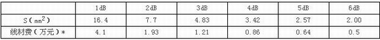
The investment caused by wire rods should actually consider the cost of line pipe and wiring construction. Table 2 does not take these considerations into account.
It can be seen from Table 2 that from the perspective of investment and construction, the line diameter of the scheme with line attenuation of no more than 1 dB is too thick and the price is too expensive, which is not easy to accept.
So, is the scale corresponding to Table 2 excessively exaggerated? no. According to our experience, 2kW / 2 km is also a common occurrence. At this time, if the line loss is calculated by 1dB, the line section will reach 131 mm2, and the broadcast line will be thicker than the power line!
Relaxing the limitation on the power transmission line attenuation, as in the above example, relaxing the line attenuation from 1dB to 3dB, not only saves nearly three times the wire, but also makes the wiring construction much easier, so the cost will be much saved.
However, the limitation on the attenuation of the power transmission line is relaxed. On the surface, a large amount of power will be dissipated on the line, so that the output power of the power amplifier must be additionally increased, and the cost of daily operation is increased. However, the actual situation is not exactly the same.
As we all know, the attenuation is relaxed to 3dB, and there is not much change in hearing. Moreover, the broadcast speakers are usually equipped with terminals with a difference of 3dB (for example, 100V terminals and 70V terminals). One of the intentions is to facilitate the adaptation to the end of the line with a large attenuation. The line terminal voltage corresponding to the 3dB attenuation is 0.707U. . When the transmission voltage is 100V and the broadcast speakers are roughly evenly distributed along the line, if the line has 3dB attenuation, a few broadcast speakers at the end of the line can use the 70V terminal for improvement. Therefore, in principle, it is not necessary to increase the capacity of the power amplifier.
In fact, before the reform and opening up, the rural cable broadcasting lines all over the country were calculated according to the terminal voltage not less than 0.63U [1], and it was normal for many years of operation.
The next question is whether it will increase the cost of daily operations. Because the loss increases, you must turn on the volume. If the loss is 3dB, it means that half of the power is lost on the line. At first glance, the electricity bill will double. actually not. Because even with a loss of 1dB, there is power consumption on the line, which is about 21%. Therefore, when the game is full, the loss of 3dB only increases the power consumption by 30%. In fact, under normal conditions, the system will generally operate at no more than a quarter of the power (such as the so-called "highest available gain" state), and the language and music signals have many low tides and pauses, thus increasing the electricity bill. It is extremely limited. As described above, with a capacity of 1000 W, the power consumption is increased by about 1 degree every 20 hours. From this point of view, it is cost-effective to treat the increased operating electricity bill as part of the “instalment paymentâ€. What's more, the above-mentioned attenuation is a "grace", and it is not required to reach 3dB. However, if the line loss is further relaxed to 6dB, the power amplifier and operating costs will become a problem to be considered.
-------------------------------------------------- ------------------------------
[1] Basic knowledge of cable broadcasting, edited by Anhui Provincial Broadcasting Administration, Anhui People's Publishing House, 1960
The relevant provisions of the "Technical Specifications for Public Broadcasting Systems (Draft)" discuss the problems related to the transmission line of the fixed-voltage public address system, and establish a line calculation model based on the actual project, and then the line section, transmission voltage and transmission loss. The issues are discussed.
I. Introduction
The constant pressure public address system is currently the mainstream of public broadcasting projects. Although some large-scale public broadcasting systems use network transmission, most of the terminals in the network and the broadcasting service area to which the system is controlled by the system are still using constant-voltage power line transmission.
With the development of the economy, there are more and more large-scale public broadcasting systems, and the coverage scale is in kilometers. For example: Tiananmen Square: 880m long from north to south, 500m (44h) from east to west; Guangzhou Zoo: 400m×1100m (about 43 hectares); 300 hectares of South China Botanical Garden; Zhejiang University: 136 hectares; Beijing Railway Station: length of each platform: about 600m Beijing Olympic Park: 680 hectares of forest park, 405 hectares of stadium center... Even indoors, some large venues such as airports, convention centers, technology exhibition halls, and large supermarkets have very large scales. Therefore, the transmission line has become a problem that cannot be ignored, and its engineering quantity and investment amount are often “overwhelming†and become the main body of the project.
There are two aspects to the engineering problem of constant pressure public broadcasting transmission lines. One is the route of the line and its topology; the other is the entity of the line, including transmission voltage, line section and line loss. This article is only for the latter.
Second, the transmission line model of constant pressure public broadcasting
Although many transmission lines for constant-pressure public broadcasting may be long, they cannot be considered as "long-term". Because the audio signal is transmitted, its theoretical frequency band is 20Hz~20kHz (the actual transmission frequency in engineering is below 12.5kHz). With its highest component, 20 kHz, the shortest wavelength of the transmitted signal is:
Where λ is the wavelength (m), C is the speed of light (m/s), and f is the frequency (Hz).
The visible wavelength is still much longer than the actual line. Therefore, the line can still be described by the lumped parameters, and the distributed reactance is also negligible. The model is shown in Figure 1.
For engineering, everyone cares about how to choose a transmission line, especially how to determine the cross section of the transmission line. There is no doubt that the line section is related to factors such as transmission voltage, load, and allowable attenuation.
Below, we use the line section as the dependent variable to build the calculation model.
1, the equivalent resistance of constant pressure broadcast speakers
Constant-voltage broadcast loudspeakers usually have two parameters: the rated operating voltage U (which must be compatible with the line transmission voltage, hence the transmission voltage) and the rated power P. Its equivalent resistance is:
Where U is the rated operating voltage (V) of the speaker and P is the rated power (W) of the speaker.
2, the gain and attenuation of the transmission line
According to the definition of gain:
Equation (4) shows that if the transmission distance and load power have been determined, in order to reduce the line cross section to save investment, the most effective way is to increase the line transmission voltage U. Each time the line transmission voltage is doubled, the line section can be reduced by a factor of four. Experience has shown that when the transmission distance exceeds 1 km, the transmission voltage of 120V to 200V should be considered, especially outdoors. In addition, a reasonable determination of the allowed transmission loss is also an important aspect.
Experience has pointed out that when the speakers are not concentrated in the line terminals, but are evenly distributed along the line, the load can be generally considered to be concentrated at the midpoint of the transmission line. At this time, the L in equation (4) can be half-estimated, and the derivation process will not be repeated. .
When the transmission voltage is 100V, the transmission line is copper wire, the broadcast speaker is evenly distributed along the line, and the transmission loss is allowed to be 3dB, the equation (4) can be simplified to
Equation (5) is very convenient for engineering applications. Please note: the unit of transmission mileage L in the formula is km, and the unit of power P is kW.
Third, the line of controversy
In the process of compiling the national standard "Technical Specifications for Public Broadcasting Systems Engineering", there are different views on the transmission losses allowed for transmission lines. Mainly 3dB and 1dB. The former believes that the transmission loss allowed by the line is too small, for example, as small as 1 dB, which will excessively increase engineering investment and increase construction difficulties. The latter believes that the transmission loss allowed by the line is too large, for example, up to 3dB, which will reduce the quality of the engineering operation and increase the operational burden. The author prefers the former.
With a transmission voltage of 100V, the total power of the load speaker is 0.5kW, and the transmission mileage is 1.0km. Using copper wire transmission as an example, the line section corresponding to the allowable attenuation is calculated by equation (4) (and wire evaluation). See Table 2.
Table 2 Line section and wire estimate corresponding to 100V/0.5kW/1.0 km
The investment caused by wire rods should actually consider the cost of line pipe and wiring construction. Table 2 does not take these considerations into account.
It can be seen from Table 2 that from the perspective of investment and construction, the line diameter of the scheme with line attenuation of no more than 1 dB is too thick and the price is too expensive, which is not easy to accept.
So, is the scale corresponding to Table 2 excessively exaggerated? no. According to our experience, 2kW / 2 km is also a common occurrence. At this time, if the line loss is calculated by 1dB, the line section will reach 131 mm2, and the broadcast line will be thicker than the power line!
Relaxing the limitation on the power transmission line attenuation, as in the above example, relaxing the line attenuation from 1dB to 3dB, not only saves nearly three times the wire, but also makes the wiring construction much easier, so the cost will be much saved.
However, the limitation on the attenuation of the power transmission line is relaxed. On the surface, a large amount of power will be dissipated on the line, so that the output power of the power amplifier must be additionally increased, and the cost of daily operation is increased. However, the actual situation is not exactly the same.
As we all know, the attenuation is relaxed to 3dB, and there is not much change in hearing. Moreover, the broadcast speakers are usually equipped with terminals with a difference of 3dB (for example, 100V terminals and 70V terminals). One of the intentions is to facilitate the adaptation to the end of the line with a large attenuation. The line terminal voltage corresponding to the 3dB attenuation is 0.707U. . When the transmission voltage is 100V and the broadcast speakers are roughly evenly distributed along the line, if the line has 3dB attenuation, a few broadcast speakers at the end of the line can use the 70V terminal for improvement. Therefore, in principle, it is not necessary to increase the capacity of the power amplifier.
In fact, before the reform and opening up, the rural cable broadcasting lines all over the country were calculated according to the terminal voltage not less than 0.63U [1], and it was normal for many years of operation.
The next question is whether it will increase the cost of daily operations. Because the loss increases, you must turn on the volume. If the loss is 3dB, it means that half of the power is lost on the line. At first glance, the electricity bill will double. actually not. Because even with a loss of 1dB, there is power consumption on the line, which is about 21%. Therefore, when the game is full, the loss of 3dB only increases the power consumption by 30%. In fact, under normal conditions, the system will generally operate at no more than a quarter of the power (such as the so-called "highest available gain" state), and the language and music signals have many low tides and pauses, thus increasing the electricity bill. It is extremely limited. As described above, with a capacity of 1000 W, the power consumption is increased by about 1 degree every 20 hours. From this point of view, it is cost-effective to treat the increased operating electricity bill as part of the “instalment paymentâ€. What's more, the above-mentioned attenuation is a "grace", and it is not required to reach 3dB. However, if the line loss is further relaxed to 6dB, the power amplifier and operating costs will become a problem to be considered.
-------------------------------------------------- ------------------------------
[1] Basic knowledge of cable broadcasting, edited by Anhui Provincial Broadcasting Administration, Anhui People's Publishing House, 1960
Storm Circuit has been producing Multilayer PCBs for over 10years. Over the years, we have seen all types of multilayer constructions from various industries, answered all types of multilayer questions, and solved all types of problems with multilayer PCBs.
Multilayer PCB is a circuit board with two or more layers. The material unlike Double-Sided PCBs with only two conductive layers all multilayer PCBs is that it must have at least three layers of conductive material, and the PCB boards are buried in the center of the material.
Benefits of Multilayer PCBs (compared to single or double-sided PCBs)
Higher assembly density
Smaller size (considerable savings on space)
Increased flexibility
Easier incorporation controlled impedance features.
EMI shielding through careful placement of power and ground layers.
Reduces the need for interconnection wiring harnesses (reduces overall weight
Multilayer PCB
Multilayer PCB,Multilayer Bga Board,Multilayer Smd PCB,Multilayer Circuit Board PCB
Storm Circuit Technology Ltd , http://www.stormpcb.com