1 Overview
In industrial control systems, the development of fieldbus technology connects intelligent field devices and automation systems with a fully digital, two-way transmission, multi-branch result communication control network, so that industrial control systems are developed in a decentralized, networked, and intelligent manner. However, due to the incompatibility between various fieldbus standards, it is impossible to achieve uniformity, which hinders the development of fieldbus technology. On the other hand, Ethernet technology, as a communication technology that monopolizes the field of office automation, has gained more and more attention and recognition from the industrial control community due to its versatility, low cost, high efficiency, high reliability and high stability. . Ethernet technology is used to achieve consistent communication from the management layer to the industrial field layer. People are used to calling the Ethernet technology applied to the industrial field "industrial Ethernet".
Industrial data communication network is different from information network. Industrial data communication must not only solve the signal intercommunication and equipment interconnection, but also need to solve the problem of information intercommunication, that is, the mutual recognition, mutual understanding and interoperability of information. The so-called signal intercommunication, that is, the communication medium, signal type, signal size, signal input / output matching and other parameters used by two devices that need to communicate with each other, and the data link layer protocol conform to the same standard, and different devices can be connected in Interconnect on the same network. If only the device interconnection is implemented, but there is no unified high-level protocol (such as the application layer protocol), then different devices still cannot understand each other and recognize the meaning of the information transmitted by each other. Interoperability between systems. Interoperability means that devices connected to the same network and from different manufacturers communicate and interoperate through a unified application layer protocol, and devices with similar performance can be interchanged. This is an important feature that distinguishes industrial data communication networks from general IT networks.
For industrial control, another important difference is real-time. An important sign of real-time is the certainty of time. The data transmission time during communication is not random, but can be determined in advance. After an event occurs, the system reacts within an accurately predictable time frame. The reaction speed is determined by the controlled process. For a system with high transmission performance, the real-time requirements are even higher.
Although Ethernet has a much higher transmission rate than the field bus, it cannot guarantee real-time communication between control devices. This is mainly because the standard Ethernet protocol is based on CSMA / CD (Carrier Sense MulTIple Access / Collision DetecTIon, carrier * multiple access / collision detection) technology, and each workstation on the network performs "*" on the bus to confirm Whether the bus is idle. If they are idle, they start sending data. If two workstations try to send data at the same time, a conflict occurs. In this case, the access mechanism first ensures that the workstation stops transmitting data, and then the workstation attempts to send the data again according to a predefined random selection algorithm. This process is repeated until the conflict disappears. The above mechanism guarantees the safe transmission of data, but from the perspective of deterministic behavior, this is a big obstacle. It allows the data transmission time to be arbitrarily postponed, which means that real-time data communication cannot be achieved. To make Ethernet technology better applied to the field of industrial control without changing its existing standards, we must find a solution to solve this problem.
To this end, major companies began to study the real-time problem of Ethernet-based communication, and each proposed different solutions. Some results have been approved by the Industrial Field Standards Committee and written into the new standard.
Here are several solutions to see how they ensure real-time communication.
2 Analysis of several solutions
2.1 Ethernet Powerlink
This solution is the solution adopted by Ethernet Powerlink proposed by Austria B & R. Ethernet Powerlink is a real-time industrial Ethernet protocol developed on the basis of Fast Ethernet. B & R's goal is to create a high-speed, real-time, deterministic network environment based on Fast Ethernet. Using high-speed cyclic data exchange, jitter is reduced to a very small (less than 1 μs), while processing acyclic data without affecting cyclic communication. Moreover, I / O and drive data can be transferred synchronously with each other and with the PCC system. Because it is completely built on standard Fast Ethernet, Ethernet Powerlink fully complies with the standard topology and physical characteristics, and can be seamlessly connected with IT technology. The transmission rate is 100 Mbps, and the minimum cycle period is 200 μs. Use standard twisted pair cable with RJ45 plug (category 5 cable). The network topology supports star, tree and daisy chain structures, and a single network segment can connect up to 240 real-time sites. Due to real-time requirements, it is not allowed to use switches, only hubs can be used as connecting devices.
2.1.1 Ethernet Powerlink message frame format
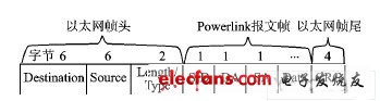
Figure 1 Powerlink message frame format
The message frame format uses the standard fast Ethernet frame header and frame tail, as shown in Figure 1. Behind the Ethernet frame header are the actual Powerlink messages, including service identification (SID), destination address (DA), source address (SA), and data (Data). The value of the Length / Type field is> 1 500, which is a reserved EtherType and is used to uniquely identify the message frame of Powerlink [1].
Among them: SID includes SoC (Start of Cyclic), EoC (End of Cyclic), PollReq, PollRes, AsyncInvite, AsyncSend, AsyncAckNack; DA is the target address; SA is the source address.
2.1.2 Working Principle of Ethernet Powerlink
Although the standard Ethernet is based on CSMA / CD technology, the working principle of CSMA / CD determines that it cannot achieve the certainty of communication, so Ethernet Powerlink introduced the SCNM (Time Slot Communication Network Management) algorithm to ensure real-time Ethernet The certainty of network communication.
SCNM allocates time slots to synchronous data and asynchronous data to ensure that only one device can occupy the network medium at a time, thereby completely preventing the occurrence of network conflicts. Ethernet Powerlink introduces management node (MN) and control node (CN) in communication management. The entire network has a unique management node, so the control node registers the configuration on the management node, the management node performs unified scheduling on the network, and allocates time channels for data communication between the various nodes. Only the management node can send data independently, and can be sent in the form of broadcast or designated; while the control node can only send data after being allowed, and only in the form of broadcast, other nodes can receive data and supervise. For real-time data, the channel time is narrow and can be accurately managed; for standard Ethernet data packets, first split into small packets, and then included in the corresponding channel for management, so the data is also deterministic [2].
The time slot communication cycle includes the start phase, synchronous phase, asynchronous phase and idle phase, as shown in Figure 2.
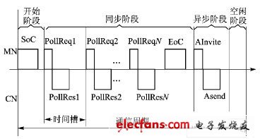
Figure 2 Powerlink communication cycle
The time of each stage is preset by the management node, and the length can be different. The management node monitors the cycle time at any time to ensure that there is no conflict at the preset time. Once the conflict occurs, it will automatically continue to the beginning of the next cycle.
Start phase: The management node broadcasts the SoC frame to start the communication cycle. After this frame is sent out, each node synchronizes accordingly. Only SoC frames are controlled by time, other frames are controlled by events.
Synchronization phase: All nodes exchange synchronization information. The management node sends a PollPeq frame to a station in a pre-defined order, requesting this node to send data; this node sends a frame of PollRes response information in the form of broadcast after being allowed, all nodes can receive this frame of data, and This frame of data is monitored, including those nodes that should get this frame of data. Both PollReq and PollRes can transmit application data. After the management node cyclically visits all nodes, it broadcasts an EoC frame to indicate the end of synchronization.
Asynchronous phase: When it is confirmed that there is no need for real-time data exchange in the queue, the system enters the asynchronous phase, and asynchronous communication mainly transmits standard Ethernet data streams. If the control node wants to send asynchronous data, it will notify the management node in the PollRes frame. The management node queries the alignment of asynchronous data requests and sends an "Asynchronous Data Send Invitation (AInvite)" to the node that wants to send asynchronous data. At this time, the control node can send asynchronous data to the designated node. The data packet sent through the time slot communication will be restored to the original data packet at the receiving node.
Idle phase: The time period remaining after the asynchronous transfer of data. During this time period, all nodes on the network are in a waiting state, waiting for the beginning of the next cycle. This time is a variable and may be 0.
The time slot communication network management introduced by Ethernet Powerlink in communication management enables each communication cycle to have a corresponding time domain for transmitting real-time data and standard Ethernet data streams. Transmit standard Ethernet data to achieve compatibility with standard Ethernet.
At present, the real-time open Ethernet Powerlink industrial Ethernet has successfully passed the IEC international standard. All documents have been approved by the IEC Organizing Committee, and Ethernet Powerlink has been included in the IEC international standards 617842, 61158300, 61158400, 61158500 and 61158600.
1.27Mm Box Header,1.27Mm Pitch Right Angle Box Header Connector,Dual Row Box Header Pcb Connecting Parts,Circuit Board Linking Materials
Dongguan City Yuanyue Electronics Co.Ltd , https://www.yyeconn.com