Due to mechanical limitations, stepper motors can sometimes stall during adaptive headlamp system (AFS) applications. Once the motor is stalled, the electronic control unit (ECU) will lose track of the headlamp position and react inappropriately, creating a very serious safety problem, so stall detection is essential in AFS applications.
The motor's back electromotive force (BEMF) can usually be used to determine whether the motor is blocked or not. BEMF varies depending on motor speed, load and supply voltage. The traditional stepper motor driver chip has no BEMF output, but includes a built-in stall detection algorithm. The customer can only set a fixed stall determination threshold in the register, which means that under real road conditions all settings must be “offline†preset before work, and cannot be adapted to real working conditions.
ON Semiconductor's NCV70522 microstepping stepper motor driver provides BEMF output through the SLA pin, which means it can perform stall detection calculations in real time and adjust the detection level according to different conditions.
Algorithm description
Since the recirculating current during coil current decay is relatively large, the coil voltage Vcoil exhibits transient characteristics. Since the application software does not always want transients, it is possible to select two operating modes by setting the bits. At high levels, the SLA pin shows a fully visible voltage transient characteristic. If the bit is cleared, then only the voltage samples at the end of each coil current crossing zero can be seen on the SLA pin. Since the transient characteristics of the coil voltage are no longer visible, this mode produces a more general BEMF input for subsequent processing by software and the like.
To adapt the sampled BEMF output level to the (0 V to 5 V) range, the sampled coil voltage Vcoil can optionally be divided by 2 or 4. This setting is controlled by the SPI bit. The figure below shows the operation of the SLA pin. The transparent bits "PWMsh" and "Icoil=0" are internal signals that together with SLAT define the sampling and sustaining moments of the coil voltage.
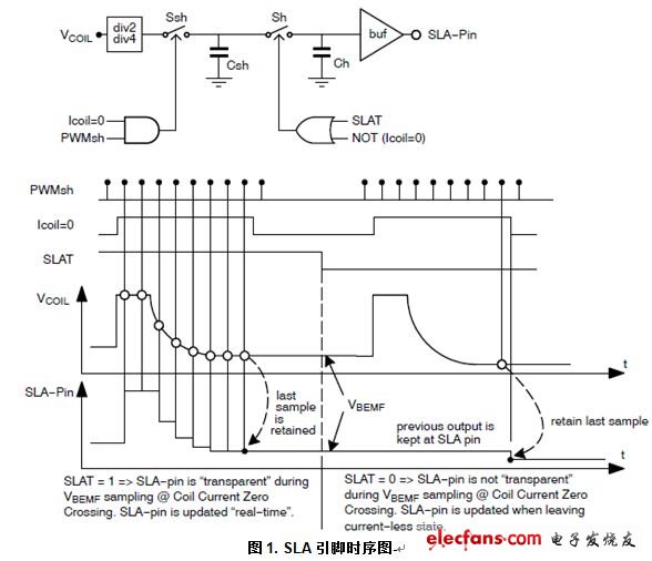
This BEMF voltage is sampled during each so-called "coil current zero crossing". Each coil has two zero current positions in each electrical cycle, so there are four zero-crossing observation points per electrical cycle, so four BEMFs can be measured. If the microstep position is at "coil current zero crossing", the BEMF voltage will only be sampled by the motor driver. The microstep position can be read via the SPI interface.
Through software, we can flexibly determine whether to stall based on the measured 4 SLA values ​​in one electrical cycle.
Portable high efficient travel charger, can charge multi devices at the same time, every port output mini 5v 1a, max 5v 2.1a. We can meet your specific requirement of the products, like label design. The plug type is US/UK/AU/EU. The material of this product is PC+ABS. All condition of our product is 100% brand new.
Our products built with input/output overvoltage protection, input/output overcurrent protection, over temperature protection, over power protection and short circuit protection. You can send more details of this product, so that we can offer best service to you!
Usb Charger,Universal Travel Adapter,Intelligent Usb Charger,Travel Adapter
Shenzhen Waweis Technology Co., Ltd. , https://www.waweispowerasdapter.com