Selection, detection and replacement of brightness delay line
After the open or short circuit of the brightness delay line is damaged, the TV will show the phenomenon that the image color is not transparent, the brightness and darkness are unclear or the brightness is out of control, the grating is darkened, and the contrast is too dark.
During the test, you can determine whether the resistance value between the input terminal and the output terminal of the brightness delay line is normal to determine whether it is damaged. Use a multimeter R & TImes; 10 kΩ file to measure the resistance value between the input terminal and the output terminal of the brightness delay line (normal value is 30 ~ 40 Ω). If the measured resistance value is infinite, it indicates that the internal of the brightness delay line is open; if the measured resistance value is close, it indicates that the internal short circuit of the brightness delay line is damaged.
After the brightness delay line is damaged, it should be replaced with the same type of delay line or another type of delay line with the same performance. If there is no brightness delay line replacement, the delay line can also be made for emergency repair.
The method of production is:
Take several pieces of aluminum foil to make a 5 & TImes; 10 mm rectangular aluminum lamination. Insert a multi-strand core wire inside and lead it out. The core wire should be in good contact with the aluminum foil. Use universal glue to glue the aluminum sheet flat to a plastic rod with a diameter of 80 mm and a length of 120 mm, and then wrap a layer of polyester film (transparent tape) on it. Use φ0.08 mm high-strength enameled wire to closely wrap 1100 T (turns) on the film-coated plastic rod, and glue two copper wires with a diameter of 1 mm and a length of 10 mm to both ends of the plastic rod with resin. Use an electric soldering iron to heat it into the two ends of the plastic rod) as the lead wire, and weld the two ends of the enameled wire to the two lead wires respectively, as the input and output ends of the brightness delay line, and the multi-strand core wire connected to the aluminum foil As a ground terminal, as shown in Figure 1. Wrap several layers of transparent tape on the wrapped enameled wire.
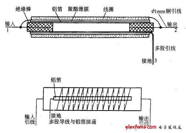
Figure 1 Structure of self-made delay line
Selection, detection and substitution of chroma delay line
After the chroma delay line is open or short-circuited, the TV will have a color "crawl" or color distortion failure.
Whether the chroma delay line is damaged by short circuit can be judged by "resistance measurement method". Use a multimeter R & TImes; 10 kΩ file to measure the resistance value between the pins of the chroma delay line. Normally, it should be ∞ (infinity). If a certain resistance value or resistance value is measured between a certain two pins, it means that the delay line has been leaked or short-circuit damaged.
The open circuit of the brightness delay line is damaged and cannot be measured with a multimeter. It can only be judged by the "component replacement method".
After the chroma delay line is damaged, the chroma delay line of the same specification and model should be replaced or replaced by another type of chroma delay line with similar performance (such as phase delay time, center frequency and Other parameters).
Guangzhou Etmy Technology Co., Ltd. , https://www.gzdigitaltalkie.com