
This series of tutorials will be combined with TI's CC254x SoC series to explain the development process of Bluetooth 4.0 from the construction of the environment to the development of the Bluetooth 4.0 protocol stack. The tutorial is divided into six parts, this article is the third part:
The third part of the knowledge points:
![]() Section XI Serial Communication
Section XI Serial Communication
![]() Section 12 Flash read and write
Section 12 Flash read and write
![]() Section 13 Introduction to the BLE Protocol Stack
Section 13 Introduction to the BLE Protocol Stack
![]() Section 14 How OSAL Works
Section 14 How OSAL Works
![]() Section 15 BLE Bluetooth 4.0 Protocol Stack Startup Analysis
Section 15 BLE Bluetooth 4.0 Protocol Stack Startup Analysis
For an introduction to TI's CC254x chip, you can click on the link below to view:
Mainstream Bluetooth BLE control chip detailed (1): TI CC2540
Recommended in the same series:
From shallow to deep, Bluetooth 4.0/BLE protocol stack development strategy (1)
From shallow to deep, Bluetooth 4.0/BLE protocol stack development strategy (2)
For the download of the tool for this article, you can go to the following address:
Zhu Zhaoyu ForARMSection XI Serial Communication
Debugging in the software development process is a very critical process, and the most common means of debugging is to print the log. There are few display devices on the embedded platform, so we need to print the information to the PC through the serial port.
MT522xboard has already connected UART0 to DB9 through RS232 chip. We only need to connect DB9 to the computer. The external device IO pin relationship corresponding to UART0 is: P0_2------RX, P0_3------ TX.
We need to configure these two IOs as multiplexed functions. The CC2540's USART can be configured in SPI mode or asynchronous UART mode. Here we need to configure the asynchronous UART mode.
First configure IO to UART mode:
PERCFG &= ~0x01; // Configure UART to position 1
P0SEL = 0x3c; // P0_2, P0_3, P0_4, P0_5 are used as serial port functions
P2DIR &= ~0XC0; // P0 takes priority as UART0
Configure the UART0 register to configure UART0 to 8N1 mode with a baud rate of 115200.
U0CSR |= 0x80; // UART mode
U0GCR |= 11; // U0GCR works with U0BAUD
U0BAUD |= 216; // The baud rate is set to 115200
UTX0IF = 0; // clear interrupt flag
U0CSR |= 0X40; // Allow reception
IEN0 |= 0x84; // open total interrupt, receive interrupt
Here, the interrupt mode is used to receive the serial port data, and the receive processing function of the application layer is called back in the interrupt.
#pragma vector = URX0_VECTOR
__interrupt void UART0_ISR(void)
{
Uint8 ch;
URX0IF = 0; // clear interrupt flag
Ch = U0DBUF;
If ( NULL != RecvCb ) // call the callback function
{
RecvCb(ch);
}
}
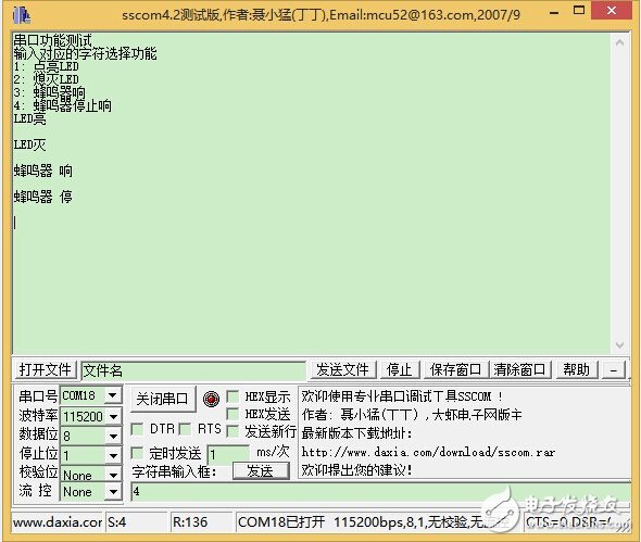
In order to test the communication function of the serial port, here we receive the command through the serial port to control the LED on and off and the buzzer sound and stop, and display the current status. According to the serial output prompt, sending the corresponding character can realize the corresponding function and display the status.
Vertical Mount Power D-SUB Connectors
ANTENK launches series vertical board mount Power-D & Combo-D D-SUB connectors machined contacts.
The ANTENK Power-D & Combo-D mixed contact d-sub connectors straight are designed for rugged / robust applications where both power & signal are required from a single connection. Featuring [Solid-Pin" machined contacts, these connectors offer high reliability performance for the most challenging design applications.
vertical board mount Power-D & Combo-D D-SUB connectors machined contacts applications
The ANTENK vertical mount combo d-sub, mixed contact connector product range is ideal for a multitude of both IP rated and non-rated industry applications. This diverse combo d-sub standard product offering includes up to 13 contact configurations (seen below) engineered for both power & coaxial connector environments such as satellite & weather stations, GPS receivers, transceivers and radio technology applications. Contact us directly for any custom or semi-custom combo d-sub connector project not listed in our standard product offering above.
Features of Vertical Mount D-SUB Connector Machined Contacts
Available in 12 industry standard sizes / positions.
Contact Antenk for other sizes / contact configurations.
Available in 10/20/30/40 amp power contacts, 5 amp signal
Allows signal, high current & high voltage in one connector.
Contacts are pre-loaded into the insulator.
Material of Vertical Mount D-SUB Connector Machined Contacts
Shell: Steel, Nickel plated
Insulator: Glass-Filled Thermoplastic, U.L. 94V-O, Black
Signal Contacts: Machined Copper Alloy, Full Gold Flash
Power Contacts: Machined Copper Alloy, Full Gold Flash
Male High Density Power D Mixed Contact Connectors, Female High Density Power D Mixed Contact Connectors, Male Standard Vertical Mount Power D-SUB Connector, Female Standard Vertical Mount Power D-SUB Connector
ShenZhen Antenk Electronics Co,Ltd , https://www.antenkconn.com