Single-phase electricity is used to power residential and office appliances, while three-phase AC (ac) systems are widely used for power distribution and direct power to higher power equipment. This article describes the basic principles of a three-phase system and the differences between possible different measurement connections.
Three-phase system
The three-phase power consists of three AC voltages of the same frequency and similar amplitude. Each ac voltage "phase" is 120° apart from the other ac voltage (Figure 1). This can be represented graphically, using waveforms and vector graphics (Figure 2).
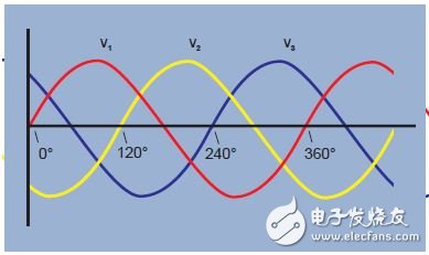
Figure 1. Three-phase voltage waveform
Figure 2. Three-phase voltage vector
There are two reasons for using a three-phase system :
1. A three-vector voltage can be used to generate a rotating magnetic field in the motor. This makes it possible to start the motor without the need for additional windings.
2. A three-phase system can be connected to the load and the required number of copper connections (transmission loss) is half that of the other methods.
Let's look at three single-phase systems, each providing 100W of power for one load (Figure 3). The total load is 3 x 100W = 300W. To provide power, 1 amp of current flows through 6 lines, so there are 6 units of losses. It is also possible to connect three power supplies to a common backhaul, as shown in Figure 4. When the load current in each phase is the same, the load is considered to be balanced. In the case of load balancing, and the three current phases are shifted by 120° from each other, the sum of the currents at any point in time is zero, and there is no current in the return line.
Figure 3. Three single-phase power supplies – 6 unit losses
Figure 4. Three-phase power supply, balanced load – 3 unit losses
In a three-phase 120° system, three wires are required to transmit power, while in other modes six wires are required. The required number of copper cables is reduced by half and the wire transmission losses are also halved.
Y-joint or star connection
A three-phase system with a common connection is generally shown in the schematic diagram of Figure 5 and is referred to as a "Y or star" connection.
A common point is called a neutral point. For safety reasons, this point is usually grounded on the power supply. In practice, the load is not perfectly balanced, and the current is transmitted using the fourth "neutral" line. Neutral conductors may be much smaller than the three main conductors if allowed by local regulations and standards.
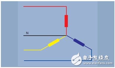
Figure 5. Y-joint or star connection – three-phase four-wire
Delta connection
The three single-phase power sources discussed above can also be connected in series. At any point in time, the sum of the three 120° phase shift voltages is zero. If the sum is zero, then both endpoints are at the same potential and can be joined together. This connection is shown in the schematic diagram of Figure 7, using the Greek letter Δ, called the delta connection.
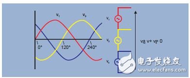
Figure 6. The sum of the instantaneous voltages at any time is zero
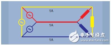
Figure 7. Delta connection – three-phase three-wire
Comparison of Y-shaped connection and delta connection
The Y-connection is used to power everyday single-phase devices used in homes and offices. A single phase load is connected to one leg of the Y-shape between the line and the neutral. The total load for each phase is shared as much as possible to provide a balanced load for the main three-phase power supply.
The Y-junction also provides single or three phase power for higher power loads at higher voltages. The single phase voltage is a phase to neutral voltage. A higher phase-to-phase voltage is also provided, as shown by the black vector in Figure 8.
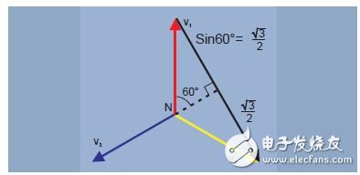
Figure 8. V phase-phase = √3 x V phase-neutral
The most common case of delta connection is to power a three-phase industrial load with higher power. However, by connecting or "striping" along the transformer coil, different voltage combinations can be obtained from the three-phase delta power supply. For example, in the United States, a 240V delta system can have split or center tap coils that provide two 120V supplies (Figure 9). For safety reasons, the center tapping point can be grounded on the transformer. Between the center tap and the third "high" of the delta connection, a voltage of 208V is also provided.
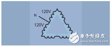
Figure 9. Delta connection with "phase separation" or "center tap" coil
Power measurement
In an AC system, power is measured using a power meter. The modern digital sampling power meter multiplies the instantaneous samples of multiple voltages and currents to calculate the instantaneous power, and then takes the average of the instantaneous power in one cycle to indicate the active power. The power meter accurately measures active power, apparent power, reactive load, power factor, harmonics, etc. over a wide range of waveforms, frequencies, and power factors. In order for the power analyzer to provide good results, the wiring configuration must be properly identified and the power analyzer properly connected.
Single phase power meter connection
Only one power meter is required, as shown in Figure 10. The connection between the system and the power meter voltage terminal and current terminal is straightforward. The voltage terminals of the power meter are connected in parallel through the load, and the current is input through a current terminal connected in series with the load.
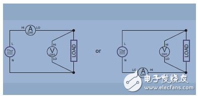
Figure 10. Single-phase two-wire and DC measurements
Single phase three phase connection
In this system, as shown in Figure 11, a voltage is generated from a centrally tapped transformer coil, all voltages being in phase. This is common in residential applications in North America, where a 240 V power supply and two 120V power supplies are provided, with different loads on each leg line. To measure total power and other quantities, connect two power meters as shown in Figure 11.
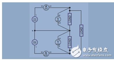
Figure 11. Single-phase three-wire
Browndale's theorem: the number of power meters required
In a single phase system, there are only two wires. Power is measured using a power meter. In a three-wire system, two power meters are required, as shown in Figure 12.
In general, the number of required power meters = number of lines - 1
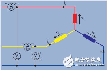
Figure 12. Three-wire Y-shaped system
Verify the three-phase Y-shaped system
The instantaneous power measured by the power meter is the product of the instantaneous voltage and current samples.
Power meter 1 reading = i1 (v1 - v3)
Power meter 2 reading = i2 (v2 - v3)
The sum of readings W1 + W2 = i1v1 - i1v3 + i2v2 - i2v3
= i1v1 + i2v2 - (i1 + i2) v3
(According to Kirchhoff's law, i1 + i2 + i3 = 0, so i1 + i2 = -i3)
2 readings W1 + W2 = i1v1 + i2v2 + i3v3 = total instantaneous power.
Three-phase three-wire connection – two power meter methods
When there are three wires, two power meters are required to measure the total power. Connect the two phases to the voltage terminals of the power meter according to the method shown in the figure.
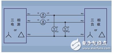
Figure 13. Three-phase three-wire, two power meter methods
Three-phase three-wire connection – three power meter methods
As mentioned earlier, although only two power meters are required to measure the total power in a three-wire system, it is sometimes convenient to use three power meters. In the connection shown in the figure, a false neutral is created by connecting the low voltage terminals of all three power meters together.
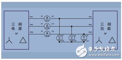
Figure 14. Three-phase three-wire (three power meter methods, setting the analyzer to three-phase four-wire mode)
The advantage of the three-wire three-power meter connection is that it indicates the power of each phase (which is not possible in the connection of the two power meters) and the phase-to-neutral voltage.
Three-phase four-wire connection
Measuring the total power in a four-wire system requires three power meters. The measured voltage is the true phase voltage. By using vector math operations, the phase-to-phase voltage can be accurately calculated from the amplitude and phase of the phase voltage. Modern power analyzers also use Kirchol's law to calculate the current flowing through the neutral line.
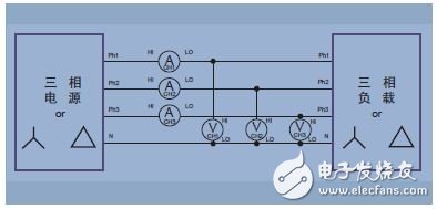
Figure 15. Three-phase four-wire (three power meter methods)
Configuration measuring device
When the number of lines is constant (N), N-1 power meters are required to measure the overall power quality, such as power. You must ensure that you have a sufficient number of channels and are connected properly.
Modern multi-channel power analyzers will use the corresponding built-in formulas to directly calculate overall power quality such as watts, volts, amps, volt-amperes, and power factor. The formula is chosen according to the wiring configuration, so setting up the wiring is critical to achieving good total power measurements. A power analyzer with vector function will also convert the phase voltage (or Y-shaped) component into a line voltage (or triangle) component. Only use factor √3 for inter-system conversion or for measurement calibration with only one power meter on a balanced linear system.
Understanding the wiring configuration and proper connection are critical to power measurement. Familiar with common wiring systems, remember that the Browndale theorem will help you get the appropriate connections and the results you can rely on.
Laptop power adapter charger for Dell:
| Laptop Model | Adapter Output |
| Latitude E5400 E5410 E5500 E5510 | 19.5v 4.62a, 7450 |
| Studio XPS 16 (1645)1640 1645 1647 | 19.5v 4.62a, 7450 |
| Studio XPS M1645 M1647 | 19.5v 4.62a, 7450 |
| XPS 14 15 17 L501x L502x L702x L702x | 19.5v 4.62a, 7450 |
| Inspiron 1464 1564 1764 | 19.5v 4.62a, 7450 |
| Inspiron 1525 1440 1526 | 19.5v 3.34a, 7450 |
| Precision M4600 M6600 | 19.5v 6.7a, 7450 |
| Inspiron N5050 N4010 N5110 | 19.5v 3.34a, 7450 |
| Inspiron 14Z-N411Z 13Z N311Z | 19.5v 4.62a, 7450 |
| Inspiron 1545 | 19.5v 3.34a, 7450 |
| Latitude E5420 E5530 E5430 E6420 | 19.5v 4.62a, 7450 |
| Inspiron 1440 1525 1526 1545 1750 | 19.5v 3.34a, Octagon tip |
| Inspiron 1300 B120 B130 | 19v 3.16a/3.42, 5525 |
| Inspiron 1525 1526 1545 | 19.5v 3.34a, 7450 |
| Studio 1440 1440n 1440z 14z 14zn | 19.5v 3.34a, 7450 |
| Latitude E4300 E4310 | 19.5v 4.62a, 7450 |
| Inspiron 13Z 13ZD 13ZR M301 M301z M301ZD M301ZR N301 | 19.5v 3.34a, 7450 |
| Inspiron N301Z N301ZD N301ZR | 19.5v 3.34a, 7450 |
| Studio 1535 1536 1555 1557 1558 | 19.5v 4.62a, 7450 |
| Latitude E5420 E5520 E6430 E6530 E6420 E6520 | 19.5v 4.62a, 7450 |
| Inspiron Mini 10 10v 1010 1010n 1010v 1011 1011n 1011v | 19v 1.58a, 5517 |
| Inspiron 14V 14VR M4010 N4020 N4030 | 19.5v 4.62a, 7450 |
| Inspiron N4110 N5110 N7110 M5010 | 19.5v 3.34a, 7450 |
| 630M 640M E1405 | 19.5v 4.62a, 7450 |
| Inspiron 15-3521 17-3721 | 19.5v 3.34a, 7450 |
| Latitude 120L | 19.5v 3.34a, 7450 |
| Vostro 1710 1710n 1720 1720n | 19.5v 4.62a, 7450 |
| Vostro 1500 1700 Inspiron 1520 1521 1720 | 19.5v 4.62a, 7450 |
| Vostro 1400 1420 PP26L | 19.5v 3.34a, 7450 |
| Latitude D410 | 19.5v 3.34a, 7450 |
| Inspiron 1120, 1121, M101 | 19.5v 3.34a, 7450 |
| Inspiron Mini 1012 1018 | 19v 1.58a, 5517 |
Our service:
Stable output and high charging efficiency.
Elegant outlook design as original one, touch smoothly and comfortable.
Original charger is good, but as a replacement, our product has more reasonable price when your original charger is broken.
And, the market of the replacement adapters becomes bigger and bigger. People would rather buy a copy one then the original because of the price.
But at the same time, people worry about that they will buy something defective. So the problem comes, how to buy a good quality one with a good price?
As a professional power adapter manufacturer, we have excellent R&D team, skilled staffs and responsible after-sale service. All your benefits can be under protected after you buy products for our company.
Our certificates :ISO9001:2008 & ISO14001:2004 , CCC , CE , FCC , ROHS.
All our products has 1 year warranty. In other words, if you get the dad products which are not damaged physically from us in one year, we will replace you the new one or the whole bulk order.
Mini Charger For Dell,Big Connector Adapter,45W Power Adapter,Dell Computer Adapter
Shenzhen Waweis Technology Co., Ltd. , https://www.waweisasdapter.com