Each conversion of the audio signal between the analog and digital domains reduces the sound quality, so keeping the audio data as digital as possible is important for optimal sound quality. The Media Oriented System Transfer (MOST) bus is designed to deliver in-vehicle audio data, but is expensive to implement and overkill for most applications. For consumer audio equipment, S/PDIF (a digital audio output interface developed by SONY and PHILIPS) is typically used to transfer compressed audio data from one audio device to another. However, the bandwidth of S/PDIF is not sufficient to deliver 5.1 or 7.1 digital audio in an uncompressed format, and there is also a lack of a proven, robust physical layer for automotive applications.
This article refers to the address: http://
The use of LVDS to transmit digital audio data is a robust, low-cost, high-bandwidth interface solution that can be easily added to existing hardware without affecting system resources. The I 2 S digital audio data that is currently available can be transmitted to different parts of the car without the actual software overhead. By keeping the audio data in digital form, multiple ADCs, DACs, and cables are no longer needed in the system, saving the cost and board space for other functions.
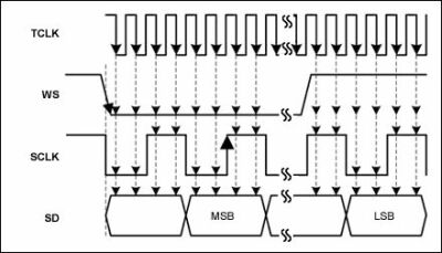 |
| Figure 1: Sampling waveform of the I 2 S input signal. |
LVDS has been used to route video data from cameras, DVD players and navigation systems to various display devices in a car. The low signal amplitude and differential architecture of LVDS allows it to transmit high bandwidth data with very low electromagnetic emissions.
The MAX9205 is designed to transmit 10-bit parallel data over a single reference clock. To transmit the I 2 S signals SCLK, WS, and SDA0-3 as data, the reference clock needs to be synchronized with SCLK and at least twice its frequency. The MAX9205 requires a reference clock frequency range of 16 to 40MHz, but the chip locks the reference clock as low as 10MHz, allowing the popular 12.28MHz clock frequency to be used.
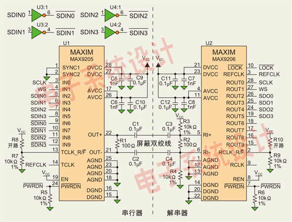 |
| Figure 2: Schematic diagram of the transmission of I 2 S audio data using the MAX9205/MAX9206. |
The signal leaving the module must be very robust in the harness and can withstand the harsh automotive environment and fault conditions. The LVDS bus is ac-coupled to avoid damage in the event of a high voltage short circuit condition. Since the MAX9205 does not automatically DC balance the output signal, make sure that the data to be transferred has been DC balanced. Of the 10 available inputs, typically no more than six are used, so the remaining four inputs can be used to DC balance the transmitted data. SCLK signal WS and the signal is symmetrical, so only the random signal fed to the inverting input terminal and SDA0-3 unused, to ensure that each two-channel to be transmitted is equal to 1 and I 2 S 0 Number of data packets.
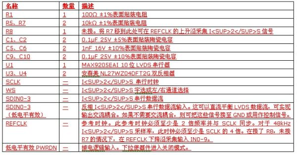 |
| Table 1: List of components and signals for the serializer circuit section. |
To meet the setup and hold times of the MAX9205 and to prevent excessive jitter on the MAX9206 deserializer output, the I 2 S signal should be sampled when it is not in transition. Connect TCLK_R/F to GND to have the MAX9205 sample the input on the falling edge of the reference clock (TCLK). It is assumed here that the SCLK state changes on the rising edge of TCLK. If the configuration is different, TCLK_R/F should be properly adjusted to ensure that the setup and hold time requirements of the input signal are met. The correct sampling waveform of the I 2 S input signal is shown in Figure 1.
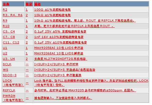 |
| Table 2: List of components and signal descriptions of the deserializer circuit section. |
Figure 2 shows the application schematic of the MAX9205 and MAX9206. The left half of the serializer circuit contains the circuitry needed to serialize and stream the LVDS audio data stream. The right half of the deserializer circuit contains the circuitry needed to receive and parallelize the LVDS audio data stream. Table 1 and Table 2 list the components and signal descriptions of the two parts of the circuit, respectively.
In summary, LVDS is the most effective on-board digital video interface and the most effective interface for transmitting audio data. The MAX9205/MAX9206 LVDS serializer/deserializer provides a simple, low-cost solution for transferring multiple I 2 S audio streams between two points in a car. Maxim's next-generation LVDS products will continue to be improved and support the transfer of control and data over the same STP line, eliminating the need for additional control interfaces.
Industry Controller PCBA,Circuit Board Assembly ,Circuit Board Manufacturing ,Printed Board Assembly
LED light Co., Ltd. , http://www.nbpcbassembly.com