With the development of automotive electronics technology, various complex electronic devices are increasingly used in automobiles. In order to improve the utilization of signals, a large amount of data information can be shared among different ECUs, and a large number of control signals can be exchanged in real time, and the conventional wiring harness is far from meeting this requirement. The CAN bus and vehicle-based communication standards based on it provide a solution to the above problems. [1] The SAE J1939 protocol is a CAN bus-based vehicle network serial communication and control protocol issued by the Society of Automotive Engineers for use in trucks and their trailers, buses, construction equipment, and agricultural equipment. A high-speed communication standard for real-time closed-loop control between electronic control units at different locations of the vehicle, the data transmission rate is 250Kb/s, the communication physical layer and the data link layer are based on CAN2.0, and the network layer and application are defined. Layer protocol. [2-3]
According to the teaching and training requirements of J1939 protocol, an automotive teaching experiment system based on J1939 protocol was constructed. The system monitors the data of the car CAN bus in real time and can completely record, display waveforms and print.
1 system principle and hardware structure
1.1 System Principle In the system, the CAN bus module system communicates with the computer through the CAN bus analyzer, and implements data acquisition and transmission for teaching and training. Students conduct experimental operations, intuitively understand data transmission and reception, master the characteristics of the CAN bus and J1939 protocol, understand the meaning and role of the physical layer, data link layer and application layer, and finally carry out system development.
The CAN bus module system can collect truck road driving status data and control power equipment such as headlights, door and window motors, and solenoid valves. The instrument panel module performs CAN communication with the vehicle body general control module and the window control module to collect the vehicle switch state, and displays various information such as the whole vehicle state, fault information, and alarm information through the LED light, the liquid crystal screen, and the turntable pointer. Human-computer interaction for real-time control of trucks.
1.2 System hardware components The system consists of three parts: J1939-based automotive CAN bus module system, including instrument panel module, body universal module, body-specific module (window control module); CAN bus analyzer, including USB-based Kvaser USB CANII bus adapter and software Warwick X-Analyser; laptop (computer).
Schematic diagram of the system hardware structure, as shown in Figure 1:
This article refers to the address: http://
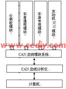
Figure 1 system hardware structure diagram
2 system hardware based on J1939 automotive CAN bus module system, the instrument panel has the function of displaying and storing the whole vehicle parameters, communicating with the engine ECU, and simultaneously implementing the process control of the load, according to the switch state on the instrument panel and connected to the vehicle body The switch and sensor status of the universal control module generate power output and communicate with the body universal control module; the body universal control module is responsible for feeding back the switch and sensor status of the region to the instrument panel module via the CAN bus, and receiving control commands to drive power. The output interface implements on-off control.
The dashboard controller on the real vehicle is located directly in front of the cab driver's seat; the front control module is located under the console between the driver's seat and the passenger seat; the body universal module is located on the frame; the window control module is located in the driving Under the console between the driver's seat and the co-pilot's seat.
2.1 Dashboard Module The Dashboard module can digitally display parameters such as vehicle speed, fuel quantity, water temperature, air pressure and engine speed. The instrument panel module can provide programmable icon display function. For example, when the vehicle speed is greater than 3Km/h and the door is not closed, the prompt message “Please close the door†is displayed at the bottom line. After the door is closed, the information disappears. It has 9 high-brightness LED symbol indicators; it has fault diagnosis function, which can monitor the bus status and electrical load short-circuit/open-circuit status in real time, display Chinese information after failure; can acquire, display and store engine-related parameters; LCD screen Real-time display of the current status information of the vehicle; 48 channels of non-isolated switching input, 6-channel resistive analog input, 3 module address line input, 1 channel ACC switch input, 1 channel 1 line temperature sensor input, 4 channels Ground control type system wake-up signal input; 6-way high-end switch output, 1 way often has electric power output, 2 way ACC file power output, 3 way B7 signal output, 1 way mileage sensor simulation signal output, 3 way sleep signal output.
2.2 Body universal control module The body universal control module has 12 non-isolated switch inputs, 1 pulse input, 1 charge indication detection input with excitation current supply; 4 resistance analog input, 4 module address line input . It has 11 high-end switch outputs, 2 channels often have electric power output, 1 channel has reverse current protection power output, and the module has safe operation mode.
The vehicle body universal control module measures vehicle travel speed and stroke, engine speed, fuel quantity, engine water temperature, front and rear axle air pressure, engine oil pressure alarm, left and right steering control and display.
2.3 window control module window control module supports 433 MHz, 868 MHz and 915 MHz communication frequency; 2 high-power full-bridge motor drive channel; 4 high-power high-side switch output channel; 12-channel switch input interface; Overvoltage and overheat protection; anti-clamp function with window drive; power interface fault diagnosis.
The input interface has 24 non-isolated switching inputs and 4 module address line inputs. The output interface has 4 high-side switch outputs, 2 channels of regular power output, and 8 full-bridge switch outputs.
2.4 CAN Bus Analyzer The Kvaser USB-CAN II is a USB-based dual-channel CAN bus analyzer with one channel for measuring high-speed CAN signals and the other for measuring high-speed CAN, low-speed CAN or single-wire CAN. The system uses a two-channel high-speed CAN analyzer (ISO 11898 compatible, TJA1050 transceiver).
Main features: fast and easy to install, plug and play; extended frame supporting 11-bit identifier standard frame and 29-bit identifier. Each CAN message is labeled with a time stamp of 10 μs accuracy. The automatic switching power supply supplies power to CAN (primary) and USB (secondary), reducing the power consumption of the notebook. Supports the "listen only" mode of the analysis tool.
Support for major operating systems Windows, WinCE and Linux. Applications support Kvaser CanKing, Warwick XA, ATI Apollo, National Instruments (NI) LabVIEW, NI DIAdem and other applications.
3 System software The system connects to the computer through Kvaser USB Can II, and uses X-Analyser for Kvaser CAN software (referred to as XA) to monitor and analyze the system bus communication message information. The raw data display interface of the car CAN bus module is shown in Figure 2. XA is used to test, analyze, simulate and monitor CAN bus and LIN bus networks. The main features are:
(1) Allow users to access and monitor bus data using various rules such as triggering, filtering, etc. on high-level protocols, such as SAE J1939, NMEA, DeviceNet, and CANopen. (2) Support the automotive industry standard file format and be compatible with related tools. (3) Perform node or network simulation by setting X-Script option or Keil interface.
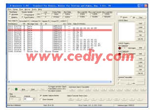
Figure 2 CAN bus raw data display interface
4 System Analysis
For the J1939 training requirements, the system can monitor the data based on the J1939 automotive CAN bus in real time during teaching, especially in actual operation, and can completely record, display waveform and print.
4.1 Display changes of the instrument panel (1) Vehicle travel speed and travel measurement and display: The system measures the travel speed of the vehicle in real time and displays the current travel speed of the vehicle on the speedometer. The speed display unit is Km/h. The input of the vehicle speed sensor is a pulse wave (the function pulse generator emits a pulse). When the input pulse wave frequency reaches 200 Hz, the vehicle speed reaches the maximum value of 180 Km/h.
When the vehicle speed is not 0, the system measures the distance traveled by the vehicle in real time and displays the multi-function display area of ​​the liquid crystal display on the instrument panel, the unit is Km, accurate to 0.1Km. At the same time, the system intermittently stores the total mileage of the vehicle in units of 1Km, which is displayed on the multi-function display area of ​​the liquid crystal display on the instrument panel.
(2) Measurement and display of fuel quantity: The fuel quantity is measured by the oil quantity sensor, and the display adopts the dimensionless mode, F means the fuel is full, and E means the fuel quantity is 0. When the resistance of the sensor changes from 0 to 200 Ω, it corresponds to F~E on the fuel gauge.
(3) Measurement and display of front and rear bridge air pressure: The system measures the front axle air pressure and the rear axle air pressure in real time and displays it on the instrument panel. The front axle air pressure and the rear axle air pressure are respectively measured by the air pressure 1 sensor and the air pressure 2 sensor. When the resistance value of the air pressure sensor changes from 0 to 200 Ω, it corresponds to 0 to 12 on the air pressure gauge.
(4) Left and right steering control and display: left and right steering is controlled by two switches. When the steering switch is turned off, the output is 5v; when the steering switch is turned on, the output is low voltage 5v, high voltage 24v pulse, and the meter The corresponding turn indicator on the board flashes.
4.2 Data Acquisition Results System XA data collection is shown in Table 1. Take the steering switch as an example: when the left turn signal is off, data is 08, and when it is on, it is alternating between 08 and 8A. When the right turn signal is on, data is 00, and when it is on, it is alternately changed between 00 and 02, as shown in FIG. A pulse is generated by a function pulse generator to simulate a change in vehicle speed, as shown in FIG.
Table 1 X-Analyser data acquisition table sensor / switch ID PGN
Speed ​​sensor 18FF0D24 0FF0D
Oil quantity sensor 18FF0C24 0FF0C
Air pressure sensor 1 18FF0C23 0FF0C
Air pressure sensor 2 18FF0003 0FF00
Left turn switch 18FF0452 0FF04
Right turn switch 18FF0432 0FF04

Figure 3 J1939 data display interface 
Figure 4 Speed ​​waveform based on J1939
5 Conclusion
This paper introduces an automotive teaching experiment system based on J1939 protocol. The system can monitor the data of the car CAN bus in real time and can completely record, display waveform and print.
In the system, the CAN bus module system communicates with the computer through the CAN bus analyzer, and performs data acquisition and transmission for teaching and training. Students conduct experimental operations, intuitively understand data transmission and reception, master the characteristics of the CAN bus and J1939 protocol, understand the meaning and role of the physical layer, data link layer and application layer, and finally carry out system development.
The author of this paper innovates: The system uses J1939's real vehicle CAN bus module system as hardware. Through the CAN bus analyzer, the data format and sensor physical value of J1939 on the module are described by an intuitive human-machine interface, so that students can quickly understand the high-level agreement and master. Key points for ECU development based on J1939. The economic benefit of the project is 100,000 yuan.
LED Street Lights,Street Lamp,LED Street Lamp
LED Bulb Light Bracket Co., Ltd. , http://www.challleds.com