See the basic tasks and requirements of the laser disc machine circuit diagram
This article refers to the address: http://
With the continuous emergence of new audio-visual equipment, the task of looking at the whole machine and the partial circuit diagram has increased. The structure of the circuit diagram of the laser disc player is very complicated, and the content that needs to be read is greatly increased. So, what is the main task of looking at the circuit diagram? What should I watch mainly? What requirements should be met? Described separately below.
First, the circuit diagram of the type and role <br> for maintenance laser disc player, usually provide various models, aircraft maintenance manual or the circuit diagram by the company, in order to facilitate analysis of the whole circuit performance, publishers often launch various circuits Atlas video disc player . These manuals and circuit diagrams mostly include circuit block diagrams, circuit schematics, etc. Only after understanding these pictures can the fault be repaired and the circuit performance analyzed. If there is no circuit diagram of the corresponding model, you can also refer to the circuit diagrams of other manufacturers or the same scheme of the company for reading.
1. Composition block diagram The block diagram represents the general composition of the entire machine or a system. The figure shows which parts it consists of, each part is represented by a square, and is illustrated by words or symbols, and the parts are connected by signal lines to indicate the relationship between them. The block diagram can roughly explain the contour of the machine, the basic working principle and the signal circulation process, but it does not see the detailed working principle and specific connection method of the circuit, and may not see the specific model and data of the component.
So what is the role of the block diagram? There are two main aspects: First, it is the first step in designing a circuit. According to the work to be done by the machine, we must first design all the circuits, and we need to make up some parts of the circuit. Each part is represented by a square, and the relationship between them is represented by a line, and then each box is designed. Specific circuit. Second, it is the basis for the user to understand the composition and basic working principle of the whole machine. If only the circuit schematic is used, it is still very difficult to analyze the composition, working process and signal flow of the machine on the basis of it. The block diagram is an integral part of the entire circuit diagram and it helps the reader to understand the whole picture. Of course, after reading the schematic diagram, the reader can also draw a block diagram.
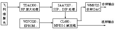
There are several cases of the block diagram of the laser disc player: it can be a simple block diagram of the whole machine, a detailed block diagram of the whole machine, or a block diagram of a certain system. For example, the simple block diagram of the whole machine means that the whole machine is composed of several systems, each system draws a box, and each system is connected by wires to express the relationship between them. This is a rough block diagram. Through the block diagram, it is easy to understand which system is composed of a whole machine. The detailed block diagram of the whole machine will make each system circuit more specific. The block diagram of each system is a more detailed block diagram which shows the system as a block of several parts of the circuit, which is the basis for further understanding the circuit structure and working principle of each system. Figure 1.1.1 is a detailed block diagram of the whole machine of our company VCD-268S. The basic circuit programs of various models and brands of disc players are the same, but the drawing method of the block diagrams can be significantly different, even if it is a simple block diagram, the drafter can purposely highlight certain circuits or signal processing.
2, circuit schematic circuit schematic diagram is a circuit diagram that uses components to combine and complete a certain working principle. In the figure, replace all the actual components with symbols, and mark the main specifications and data on the side, and replace the connecting wires with wires. Since the use of integrated circuits in a large amount, the internal circuit of the integrated circuit is very complicated, and it is too difficult to directly draw the internal circuit structure. When drawing the circuit diagram, the integrated circuit is regarded as a special component, and the functions in the integrated circuit are represented by a block diagram. At this point, the shape of the circuit schematic has been deformed, and the original practical circuit diagram has been changed to a circuit diagram combining the practical circuit diagram and the square.
There are two main uses for schematics. First of all, it is a must for making electronic devices. To make an electronic device, various components must be connected according to certain rules. This rule is a variety of electronic circuits, that is, schematics. The second use allows the reader to study the ins and outs of the circuit well, understand the flow process and processing of the electrical signal in the circuit, and then analyze the working principle of the machine. The above circuit diagram is also called a practical circuit diagram. Sometimes, in order to analyze the working principle of the circuit, the practical circuit is simplified, the auxiliary circuit or component is removed, and the original circuit backbone is retained. Such a circuit is often called a schematic circuit or a basic circuit diagram.
3, printed circuit board diagram printed circuit board diagram is also called installation diagram. The circuit schematic can only explain the working principle of the circuit, can not see the specific shape of each component, do not know the connection of them in the machine, can not see where these components should be installed. Printed circuit board diagrams solve these problems and are very close to the actual component installation and connection. Printed circuit board diagram is to draw the symbol of the actual component to the position where the component should be, and use the circle to indicate the wiring hole of the component pin, replace the connecting wire with the copper foil strip on the printed circuit board, and its direction The position and shape are the same as the actual ones.
4. The wiring diagram of the board is often composed of multiple printed circuit boards because the circuit of the whole machine is very complicated. Various printed circuit boards, various displays, various buttons, various input and output jacks, etc., have many connections between them, and it is difficult to know what effect each connection has. The various figures above do not solve this problem very well. To this end, the block connection diagram of the whole machine has been added, and the connection is mostly realized by the connector. Thus, it is only necessary to indicate that each line is connected from the first leg of the first socket of a printed circuit to the first leg of the other socket of the other printed circuit board, and the signal is marked with simple letters and symbols. The content can clearly indicate the ins and outs of the signal. In fact, the wiring diagrams and letter and symbol marking methods of various manufacturers may differ from each other, but as long as they are carefully scrutinized, the signal direction and the connection between the circuits can be seen.
Second, the basic tasks of reading the circuit diagram of various video disc players <br> The circuit diagram of a video disc player is very cumbersome and huge. What should you watch when looking at the circuit diagram? The circuit structure is from small to large, from simple to complex, and can be divided into the following four levels of reading tasks, which are unit circuit, system circuit, block circuit and whole machine circuit. The key points of reading these circuit diagrams are both the two aspects of reading the block diagram and the practical circuit schematic. Reading the block diagram is the premise and basis for reading the schematic diagram of the circuit.
1. Read unit circuit The whole machine is composed of several unit circuits. The unit circuit is composed of various components. The reader should be familiar with and keep in mind the graphic symbols of various components. When analyzing the unit circuit, we should pay attention to the following problems: the position and function of the unit circuit in the whole machine; the structure and specific tasks of the unit circuit; if it is a discrete component circuit, the role of each component in this circuit should be clear; It is necessary to clarify the input and output signal content and characteristics of this circuit, and to grasp the changes in waveform, amplitude, frequency or voltage after the signal passes through this circuit.
The laser disc player uses a large number of integrated circuits, and many unit circuits have been integrated on the chip, which brings convenience to the analysis unit circuit. For the integrated unit circuit, our main task is to master its function and signal transformation law, without having to care about its circuit structure and specific working process. When looking at the circuit diagram of the discrete unit, it is often difficult to analyze the circuit principle, which often becomes a difficult point to look at the circuit diagram.
2, the reading system circuit consists of several unit circuits can form a circuit system, the circuit system can complete the function of a certain system in the whole machine. When reading the circuit system, it is necessary to clarify the main functions and tasks of the circuit system, the composition of the unit circuit, and the processing and transformation process of the signal. After clearing these contents, it laid a solid foundation for reading the whole circuit. For example, the servo system of a laser disc player, the task of which is to ensure good focus, tracking, radial glide and spindle CLV servo control of the laser head. It mainly includes several circuits such as focus servo, tracking servo, feed servo and spindle servo, and each servo circuit includes unit circuits such as servo error signal generation and drive amplification. After the complete servo system is composed of unit circuits, it becomes an extremely important auxiliary control system in the laser disc player. The failure of the laser disc player is mainly caused by the failure of the servo system.
A complete circuit should consist of several circuit systems. When reading a specific circuit system, you should first read the block diagram of the system. If the system block diagram is not given, the reader should be able to draw a block diagram of the system by reading the process.
Before diving into the circuit diagram of this system, you must first read the block diagram of the system. If the block diagram of the system has been given, it will bring great convenience to the reading system circuit diagram. When reading the block diagram, first find the signal input and output, and clarify the characteristics of the input and output signals. Then, analyze the boxes one by one, understanding the role of each box (usually a unit circuit), how the signal changes at that level, and what the relationship between the boxes is. After clarifying these issues, the general composition and signal processing of the system is clear. In the analysis of each box, some of the boxes are marked with circuit names, such as "RF amplification", "video encoding and conversion", "decoding circuit", etc.; some indicate the role of the circuit, such as "inverter ", "clock", "karaoke" and so on. No matter how you mark it out, you should understand the role of each box in the analysis. On the basis of reading the system block diagram, the block diagram is compared with the schematic diagram, and each box in the block diagram is mapped with the specific circuit in the schematic diagram, which lays a foundation for the next step of analyzing the schematic diagram.
On the basis of reading the system block diagram, it is necessary to read the system electrical schematic. When reading the system electrical schematic, you should also find the signal input and output, and make clear the characteristics of the input and output signals. Based on this, the unit circuits corresponding to each box are analyzed step by step. The actual circuit traces may be more complicated. There may be a main path and an auxiliary path. There are direct or delayed, and there are main paths or feedback paths. When analyzing the circuit, it is necessary to analyze them one by one. After reading the circuit step by step, be sure to go through the signal circulation process from beginning to end to deepen understanding and re-verify.
When taking the signal flow diagram, you must first take the signal of the main circuit. This kind of reading can highlight the main problem and clarify the main processing of the main signal. If you do not go through the main signal and the auxiliary signal, it is likely to mess up the main signal flow. When walking the signal flow diagram, you should also analyze the waveform changes of the signal while walking. In the signal processing process, depending on the need, the signal waveform changes, and some of the signal amplitude changes. When the signal waveform changes, a new signal is generated, and the signal produces a qualitative change. When the signal waveform does not change, but the magnitude of the amplitude changes, the signal does not change intrinsically.
Since the laser disc player uses many integrated circuits, it is impossible to manufacture the integrated circuit only by considering the flow of the signal of the system, and some circuits of the same nature are often implemented in one integrated circuit. The order of the circuits may not be exactly the same as the sequence of the signals. The flow of the signals may jump and jump, and the lines will cross each other, which brings certain difficulties to the read signal flow chart. When looking at the signal flow diagram, it is best to draw the signal with a color pen while walking, and you can see it at a glance.
In order to truly understand the circuit diagram of each system of the whole machine, only the above analysis is not enough. It must be verified and tested on the basis of the above analysis. Only in this way can the correctness of the analysis be confirmed, and the understanding of the circuit can be deepened. Prepare for future repairs. The test points should include the input and output points of the entire system, the input and output points of each unit circuit. On the circuit diagram, important test points are marked with a circle in the figure and marked with the letter "TP" next to it. During the test, find the corresponding position on the printed circuit board according to the signal flow direction and test point of the schematic diagram, and test the waveform and amplitude of the signal with an oscilloscope (or measure the voltage value with a multimeter) and compare it with the principle. Usually, there are some differences between the measured waveform and the theoretical waveform, which is normal.
3, read the block circuit The practical circuit of the laser disc player is very complicated, usually can not use a circuit diagram to completely draw all the circuits. In order to facilitate the organization of production and assembly, the manufacturer often divides the whole machine into several plates (or modules), each of which contains one or several circuit systems, and often draws a practical circuit of one plate on a circuit diagram. Each plate is connected by a connector, and is also represented by a specific graphic and letter mark on the circuit. Generally, on each of the plates, all the circuits of the block can be composed with a large medium-sized scale or even a very large-scale integrated circuit centered on the peripheral components and auxiliary circuits.
For example, a complete VCD disc player, mainly consisting of system controller, laser reading system, servo system, digital processing system (CD-DSP), VCD decompression system, audio (including karaoke) system, power supply system and machinery System and other components. A complete machine often distributes various circuit systems into several sections (or modules). The typical method is to focus on one part of the laser reading system, servo system, CD-DSP system and system controller (or part). The circuit board is called a CD module. The VCD decompression system is a very complicated giant circuit system. The VCD decompression circuit and the system controller (the other part) are placed separately in a circuit called a decompression board or a decoder board. In addition, the power circuit and audio (including karaoke) system can be placed on another circuit board. In the practical video disk machine, operation and display circuits are also provided, and a printed board is often used alone. Thus, the circuit system of each of the above printed boards can be divided into a circuit diagram, and each circuit diagram is called a block (or module) system circuit diagram.
When reading the block circuit diagram, it is first to read the block diagram of the block circuit, and then read the circuit schematic. When reading, it mainly reads the circuit system composed of those circuit systems, analyzes the tasks, circuit programs and signal transformation processes of each circuit system.
4, read the whole machine circuit on the basis of reading the circuit diagram of each board, but also read the whole machine circuit diagram, because the whole circuit is very complicated, it is difficult to draw all the circuits of the whole machine onto a drawing. The printed circuit board is not a piece. Read the whole machine diagram, including the block diagram of the whole machine, the block connection diagram and the schematic diagram of the whole machine. The key to reading is often the block diagram of the whole machine. The block diagram of the whole machine is divided into two parts: the simple composition block diagram and the detailed composition block diagram. The detailed block diagram is very important for reading the schematic diagram of the whole circuit.
The purpose of reading the block diagram of the whole machine is to understand the whole picture of the whole machine. By reading the block diagram of the whole machine, we can see the basic composition of the whole machine and the connection between the parts. We can also see the connection between the whole circuit (and signal) and the outside world. This is also the final task of reading the block diagram. According to the foregoing, the basis for reading the whole machine diagram is to read the block circuit diagram and the system circuit diagram. The local circuit diagram is clear, and the whole machine diagram can be completed.
Third, look at the requirements of the circuit diagram <br> See what requirements should be achieved in the circuit diagram? There are several levels depending on the depth and breadth.
1. First of all, the block diagram of the whole machine and the schematic diagram of the whole machine must be “checked inâ€.
The whole block diagram is a simplified diagram of the whole machine, which embodies the connection between each unit circuit and system circuit and the signal processing process. The reader must first "put the block diagram of the whole machine block diagram with the whole machine circuit diagram", that is, according to the block diagram, the position and circuit range of the corresponding specific circuit on the whole machine picture can be found. The habits of the various drawing people are different. The drawing of the same circuit may be different, or the position on the whole machine diagram (or the panel diagram) is different, and even a circuit is divided into several places. The reader should be able to recognize the specific circuits corresponding to the block diagram in the whole circuit, and set the position, name and circuit range of each specific circuit to the upper number.
For those who only have a preliminary understanding, it is ok to meet the above requirements. But for professional maintenance personnel, this is not enough, and should meet the following requirements.
2, to be familiar with circuit functions, programs and signal transformation rules should be familiar with the main functions of each unit circuit and circuit system. Sometimes, circuits of the same function can have several different circuit forms and circuit programs, and should be familiar with the structural features of various circuit forms. For example, there are two major types of servo circuit systems, one is analog servo system (early production model), which uses traditional analog signal processing method to realize servo head servo; and the other is digital servo system. The digital signal processing method is used to realize the servo of the laser head. The tasks of the two servo systems are the same, but the circuit program and the signal processing process are obviously different, and each has its own characteristics.
You should also be familiar with the characteristics of the signal frequency, amplitude and waveform on each circuit. By analyzing the transformation process of the signals on each circuit, we can deeply grasp the basic functions of the circuit and the advantages and disadvantages of the circuit. In the signal path, the frequency, amplitude and waveform of the signal are constantly changing, and each circuit has different index requirements for the signal. Only by mastering the signal transformation rules on each circuit can you really understand the circuit diagram.
3, understand the relevant data of the circuit and components to see the higher standards of the requirements, not only to be familiar with circuit functions, programs, not only to be familiar with the general rules of waveform transformation, but also to understand the relevant data of circuits and components, made " There are counts in my heart." For some important parts of the circuit, to understand its DC static operating point, it is also necessary to understand its voltage value under dynamic conditions. By analyzing and comparing the static and dynamic voltage values, you can grasp the working characteristics and working state of the circuit. Pay attention to the static and dynamic DC voltage values ​​of each pin of the integrated circuit. Especially for the input and output pins of the signal path, the voltage value directly affects or determines the performance of the circuit. The data about the critical test points on the circuit should be kept in mind, including static, dynamic DC voltage values, frequency (cycle), amplitude, pulse width, etc. of the signal.
As a professional worker, you should also meet higher requirements when looking at the map. By mastering the circuit diagram and related data, you should be able to quantitatively estimate the main parameters and electrical performance of the circuit. Generally, amateurs or maintenance personnel can't reach this requirement, but they should master more of this knowledge and it will be beneficial in the future.
3Pans Buffet Server,Electric Warming Tray Buffet Server,Buffet Server Warming Tray,3Pans Buffet Server Warmer
Shaoxing Haoda Electrical Appliance Co.,Ltd , http://www.hotplates.nl