The role of the half bridge drive circuit:
The function of the half-bridge driving circuit is mainly to generate an alternating current trigger signal through the power tube, thereby generating a large current to further drive the motor. Different from the single-chip drive, the single-chip drive has limited capability and is generally only used as a drive signal.
Half bridge drive circuit works:
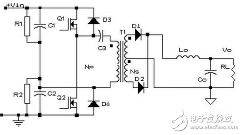
Basic topology circuit diagram of half bridge circuit
The capacitors C1 and C2 form a bridge with the switching tubes Q1 and Q2, and the diagonal of the bridge is connected to the primary winding of the transformer T1, so it is called a half bridge converter. If C1=C2 at this time, when a certain switch is turned on, the voltage on the winding is only half of the power supply voltage.
The working process of the circuit is roughly as follows:
Refer to the basic topology circuit diagram of the half-bridge circuit, in which Q1 is turned on and Q2 is turned off. At this time, the voltage applied across the transformer is half of the bus voltage, and the energy is transmitted from the primary side to the secondary side.
Q1 is turned off, and Q2 is turned off. At this time, the two windings of the secondary side of the transformer are in a short-circuit state due to the simultaneous free flow of the two tubes of the rectifier diode, and the primary winding is also equivalent to the short-circuit state.
Q1 is turned off and Q2 is turned on. At this time, the voltage applied across the transformer is also substantially half of the bus voltage, and the energy is transmitted from the primary side to the secondary side. The two diodes on the secondary side complete the commutation.
Points to note
Bias problem
Reason: Since the potential of the two capacitor connection points A floats with the Q1 and Q2 conduction conditions, the volt-second value of each transistor switch can be automatically balanced. When the floating does not meet the requirements, it is assumed that Q1 and Q2 are different. The switching characteristic, that is, under the same base pulse width t=t1, Q1 is turned off slowly, and Q2 is turned off faster, then the voltage at point B will be affected, there will be A1, A2 in the gray area. The unbalanced volt-second value is due to the Q1 turn-off delay.
If this unbalanced waveform is used to drive the transformer, a bias phenomenon will occur, causing the core to saturate and generate excessive transistor collector current, thereby reducing the efficiency of the converter and causing the transistor to run out of control or even burn out.
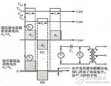
Working waveform of a capacitor connected in series with the primary side of the transformer
Solution: Add a series capacitor C3 to the primary winding of the transformer, and the DC bias proportional to the unbalanced volt-second value will be filtered by the secondary capacitor, so that the voltage will be balanced during the transistor conduction period. Value, to achieve the purpose of eliminating the bias.
Two capacitors used as bridge arms:
From the perspective of the half-bridge circuit structure, when selecting two capacitors C1 and C2 on the bridge arm, it is necessary to consider the voltage equalization problem of the capacitor. Try to use the capacitor of C1=C2, then when a certain switch is turned on, the voltage on the winding Only half of the power supply voltage achieves the voltage equalization effect. Under normal circumstances, a resistor (R1 and R2 in the schematic diagram) is connected in parallel at both ends of the two capacitors, and R1=R2 further satisfies the requirement. And power should pay attention to derating. At this time, the functions of capacitors C1 and C2 are used to automatically balance the volt-second value of each switch tube (the difference from C3: C3 is to filter out the DC component that affects the volt-second balance).
Straight through problem
The so-called straight-through is the phenomenon that Q1 and Q2 are simultaneously turned on at a certain moment, and a short circuit is formed at this time.
solution
The maximum value of the drive pulse width can be limited so that the conduction angle does not cause a through.
It is also possible to solve the problem topologically, and then use the cross-coupling closed circuit so that when one tube is turned on, the other tube is driven in a closed state until the previous tube is turned off, the sealing is cancelled, and the rear tube is turned on. This automatic blocking has the advantage of automatic adaptation to storage time and parameter distribution, and can be used for full duty cycle.
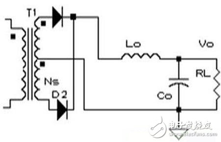
Full-wave circuit
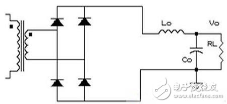
Secondary bridge
The choice of the two circuits is mainly to consider the following two points:
1. Consider the safety of the pipe according to the level of the output voltage;
2, the problem of power loss, mainly the loss of the switch tube and the secondary winding;
Half bridge circuit drive problem:
1, the primary side coil overload limit: to provide independent current limit to the original power tube;
2, soft start: start, limit the pulse width, so that the pulse width slowly rises in the first few cycles of startup;
3, magnetic control: control transistor drive pulse width is equal, to make the forward and reverse magnetic flux equal, no bias;
4, to prevent straight through: to control the upper limit of the duty cycle to reduce;
5, voltage control and isolation: the circuit should be closed-loop control, isolation can be optical isolators, transformers or magnetic amplifiers;
6. Overvoltage protection: usually the switching pulse of the closed converter is used for overvoltage protection;
7. Current limit: The current limit is installed on the input or output circuit and acts when a short circuit occurs;
8, the input voltage is too low protection: the regulation can only be started under a sufficiently high voltage to play good performance;
9, in addition, there must be appropriate auxiliary functions: such as inrush current limiting and output filtering.
Driving characteristics of the half bridge circuit:
1. The upper and lower bridge arms are not common, that is, the switch tubes of the primary circuit are not common.
2. Isolation drive.
Advantages of EPON:
EPON adopts a point-to-multipoint structure and passive optical fiber transmission mode to provide multiple services on Ethernet. EPON technology integrates low-cost, high-bandwidth Ethernet equipment and low-cost optical fiber network technology. Compared with other access technologies, it has unique advantages, which are mainly reflected in the following aspects.
Good compatibility: EPON uses Ethernet technology, which is by far the most successful and mature LAN technology, and it can be said to be the mainstream of user LAN technology. Because EPON is only based on the existing IEEE 802.3 protocol, and realizes the transmission of Ethernet frames in the user access network through minor modifications and additions, EPON is basically compatible with Ethernet technology. Using Ethernet as the access network has low cost and good versatility, avoids complicated transmission protocols and format conversion, high efficiency, and simple management.
Low construction and maintenance costs: The EPON system significantly reduces the number of optical fibers, optical transceiver modules, and central office equipment. As the cost of optoelectronic devices continues to decrease, EPON`s per-line equipment access cost is comparable to ADSL and CM, especially the current price of optical fiber is lower than that of cable. These conditions have become the basis for the development of FTTH. At the same time, the foundation of EPON is Ethernet, and related components and equipment of Ethernet are the lowest in price. Using EPON as the access network has low cost and good versatility, eliminating the need for IP data transmission protocol and format conversion. High efficiency and simple management. In addition, there are only passive optical components such as optical fiber and optical splitter between the central office (OLT) and the user (ONU). There is no need to rent a computer room, no power supply, and no active equipment maintenance personnel. Therefore, it can effectively save operation and maintenance. cost.
High bandwidth: EPON can currently provide a downlink transmission rate of 1. 25 Gb/s, a single-wavelength uplink rate of 125 Mb/s, and can be upgraded to 1 GB/s with the development of Ethernet technology. This is much higher than the current access methods, which can meet the bandwidth requirements of various services such as broadband Internet access, video on demand, online games, video phones, and digital high-definition televisions, and fully meet the bandwidth requirements of access network customers. And it can easily and flexibly allocate bandwidth dynamically according to changes in user requirements, which can be used as the user's ultimate access method.
Epon Olt,4 / 8 Port Olt,Network Device Olt,Uplink Port, OLT DEVICE
Shenzhen GL-COM Technology CO.,LTD. , https://www.szglcom.com