The use of single-chip microcomputer serialization will introduce the structure and use method of effectively using the peripheral functions of the single-chip microcomputer, which will enable us to learn the basic peripheral functions common to all kinds of single-chip microcomputers, and can be widely applied to various aspects. The microcontroller can't run by CPU and memory only! This article describes GPIO and serial communication.
What is the "peripheral function" that is indispensable for the effective use of a microcontroller?
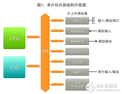
As described in the series of "Introduction to Microcontrollers" serialized in the past, the microcontroller that controls the electronic product is composed of CPU, memory and peripheral functions (Figure 1). The CPU executes operations, reads and writes data, and determines conditions based on instructions (programs), while memory is used to store the program (memory).
Peripheral functions refer to various functions for making the microcontroller easy to use. For example, in order to exchange signals with external sensors and switches, the CPU requires a peripheral function such as an "input/output port (I/O port)".
Moreover, the "A/D converter" that converts the analog input signal into a digital value and the "D/A converter" that converts the digital value to an analog output signal in turn are indispensable for the microcontroller to process various signals. Peripheral features.
In addition, there are "timers" for correct time measurement and "real time clock (RTC)" for date and timepieces for time-related processing, in addition to parallel signals and strings. A "UART (Universal Asynchronous Receiver Transmitter)" that exchanges serial signals for communication.
In this series, we will use the Renesas electronic microcontroller-RX63N as an example to introduce the basic knowledge of peripheral functions that make the microcontroller easier to use. We will use the electronic board "GR-SAKURA" equipped with the "RX63N" ​​program for explanation. Please try it out for practical operation!
Understand the input/output port of digital signals---"GPIO"
In the "input/output port (I/O port)", the input/output port of the digital signal, "GPIO (General Purpose Input/Output)" is also called "general purpose I/O port", which is used for Very convenient port for digital signal input/output. It is used to transmit the digital output sensor value and the ON/OFF value of the switch to the input end of the MCU and display the operation result of the MCU through the LED, and output the signal for driving the motor to run, and so on.
A GPIO is called a general-purpose port whose pins can be used for both input and output. In earlier microcontrollers, pins were pinned for input or output, but many microcontrollers are now free to set them as input or output ports. Assuming that the GPIO terminal has 8 pins, 4 pins can be used for input, the other 4 pins can be used for output, or 1 pin can be used for input, and the remaining 7 pins are used for output. .
In GPIO, in order to exchange data between the CPU and an external device, conversion of a digital value (0 or 1) processed by a program and a signal (a LOW level or a HIGH level of a voltage) is mutually performed. The following is the role of the register (*1) that is the basis of the GPIO port of the RX63N microcontroller (Figure 2).
(*1) Register (Register): A memory loop that exists in the CPU and peripheral functions of the microcontroller. Used to calculate and maintain the execution state of the CPU. Since it is an internal loop functioning as a CPU and peripheral functions, it is fast in writing and reading memory, but its capacity is very small. It has registers (general-purpose registers) that can be used for various purposes, and is useful. Special registers for certain defined functions and uses.
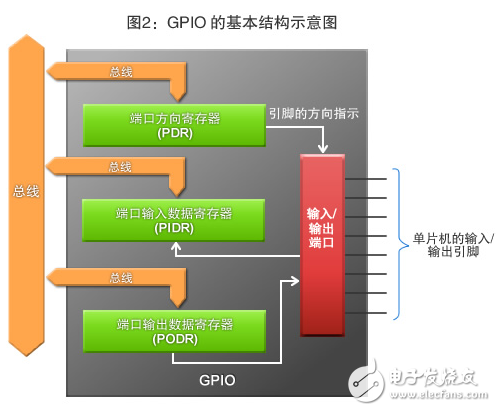
Port Direction Register (PDR)
A register that determines the direction of the pin, also known as a "direction register."
Port Input Data Register (PIDR)
A register that reflects the state of the pin used when input. When the LOW level or HIGH level is input from the pin, it is converted to a value of 0 or 1 and the conversion result is read. The value will also change as the pin changes. Therefore, the value at the time of reading will not be maintained.
Port Output Data Register (PODR)
This register holds the output data used as an output pin. The value of 0 or 1 is converted to a LOW level or HIGH level signal and output from the pin. Since the pre-rewrite value can be maintained as with memory, the output voltage from the pin will remain unchanged until overwritten.
Circuit Breaker is a switching device that can close, carry and break current under normal circuit conditions and can close and carry current under the abnormal loop conditions within a specified time.
The circuit breaker is generally composed of a contact system,an arc extinguishing system, an operating mechanism,a trip unit,a casing,and so on.Our company's Circuit Breakers had been divided into 11 series(as follow),every series product have it's own special function,had exported into global market for many years,always with good feedback.
Mini Circuit Breaker
Eearth Leakage Circuit Breaker
High Breaking Capacitor MCB
ID Residual Current Circiut Breaker
F360 Residual Current Circuit Breaker
Motor Protection Circuit Breaker
CM1 Moulded Case Circuit Breaker
NS Moulded Case Circuit Breaker
S Moulded Case Circuit Breaker
PX Moulded Case Circuit Breaker
Air Circuit Breaker
Circuit Breakers,Air Circuit Breaker,Earth Leakage Circuit Breaker,Moulded Case Circuit Breaker
Ningbo Bond Industrial Electric Co., Ltd. , https://www.bondelectro.com