Circuit function
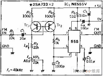
Frequency modulation can be performed by changing the charging current of the 555 self-excited multivibrator. It is worth noting that if the charging current is changed drastically, it can also be used as a VCO. The oscillation frequency of this oscillator is below 100KHZ, and the frequency of this circuit is 40KHZ, which is close to the infrared remote control frequency. This circuit can also be used as a frequency sound or data signal for low frequency carrier modulation.
Circuit working principle
If the modulation frequency range is small, the resistor is connected to the lead 7 of the 555 oscillating circuit and connected in series with the DC blocking capacitor to constitute FM modulation. This circuit uses a current Miller circuit composed of TT1 and TT2 to generate a charging current in the charging circuit. The current is determined by R2 and VR1. The low frequency modulated signal is superimposed with the bias current IB to change the oscillation frequency.
The current Miller circuit should use two transistors as much as possible.
Surface Mount Power Outlets,Surface Tabletop Socket,Surface Installation Power Socket,Surface Mounted Power Strip
Dongguan baiyou electronic co.,ltd , https://www.dgbaiyou.com