A blood invisible to the naked eye, but how much water vapor droplets around us can cause damage to the LED lamp bead? Maybe you will be alarmist, but the facts tell us that many LED display accidents are caused by these insignificant droplets.
How serious is a small waterdrop on LED products?The moisture in the atmosphere penetrates into the interior of the packaging material of the LED lamp beads by diffusion. When the SMD LED device is mounted on the PCB through the chip, it is flowed into the reflow oven for reflow soldering. In the reflow zone, the entire device should be above 183 degrees 30-90s, the maximum temperature may be 210-235 degrees (SnPb eutectic), the peak of lead-free soldering will be higher, around 245 degrees. Under the high temperature of the reflow zone, the moisture inside the LED device will expand rapidly, the matching between different materials of the device will be lost, and various connections will cause bad changes, which will cause the LED device to peel off or burst, so the device Electrical performance is affected or destroyed.
In the case of severe damage, the appearance of the device is deformed, cracks, etc., and in most cases, it is invisible to the naked eye. But as time goes by, the crack will crack more and more, and eventually the circuit will be bad.
How serious is a small waterdrop on LED products? (illustration)1. After prolonged exposure in air: moisture penetrates into the device packaging material
2, reflow soldering start: Temp
3, with the increase of temperature: Temp "100 ° C, water evaporation, pressure sudden increase, leading to stripping
Scaling phenomenon
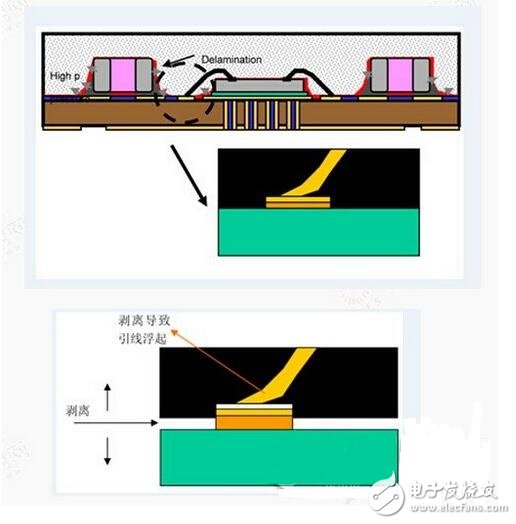
Lead stripping
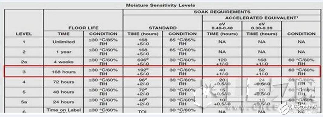
In order to detect that the LED lamp beads manufactured by the packaging factory have sufficient moisture resistance and avoid the above-mentioned lead stripping phenomenon, IPC/JEDEC defines a standard "humidity sensitivity level" as follows. Those who need it can also go to the JEDEC official website. Download J-STD-020D.1.
This document identifies the level of stress-sensitive classification of unsealed solid-state surface mount devices (SMD) that is used to determine the level of classification that should be used for initial reliability identification. Once the classification level is determined, SMD devices can take appropriate action during packaging, storage, and handling, and avoid thermal and mechanical damage during assembly solder reflow attachment and/or repair operations.
MSL (Moisture SenTIvity levels), from small to large, the smaller the number, the better its humidity resistance; the larger the number, the shorter the time it can be exposed to ambient moisture.
According to the MSL standard, the display factory and the engineering manufacturer can easily pick a qualified lamp, and have clear regulations on the packaging, storage and handling of the LED lamp in the subsequent processing. Because this standard has high requirements on the quality of LED lamp beads, there are very few packaging companies that dare to adopt. There are Curry and Nichia in foreign countries, and Mecca, Lehman and Lanke in China.
As an example of level 3, if the part is exposed to an environment within 30 ° C and 60% humidity, the storage time should not exceed 192 hours (including the 24-hour exposure of the LED package factory). Time, so the LED display factory only has 168 hours (=192-24) of workshop time), which means that for the level 3 LED components to be removed from the vacuum packaging, it must be played within 168 hours. And after the Reflow (reflow soldering). If Reflow cannot be completed within the specified time, it must be repacked, preferably after re-baking, because the time after re-baking can be reset to zero. If it exceeds the specified time, it must be re-baked before it can be used.
Destroying an LED display does not require strong storms, and a small drop of water is enough.
How to set up LED digital tube driver?When driving the LED, it should be divided into two cases, such as the common anode connection method and the common cathode connection method. When the anode is positive, the positive terminal of the LED is connected to the positive power supply, and the negative terminal is connected to the P port through a current limiting resistor. Resistor, as long as this current limiting resistor is appropriate, the current is from the power source - LED - current limiting resistor - P port, P port is low potential LED when the current is not flowing, P port is a high-potential or high-resistance state common cathode connection method, the LED negative terminal is grounded, and the positive terminal is directly connected to the P port. At this time, a pull-up resistor is connected. This pull-up resistor is used for providing LED illumination, and the current when the illumination tube is bright. It is from the power supply - pull-up resistor - LED - ground. At this time, the pull-up resistor is also used for current limiting. When the P port is high-potential or high-resistance state, when the light-emitting tube is dark, the current is from the power source - the pull-up resistor - P port. At this time, the LED has no current flowing, the P port is low, and the current limiting resistor flows over the current. Flowing in from the P port.
Start with the output drive capability of the microcontroller. The output driver of the single-chip microcomputer is divided into two modes: high-level drive and low-level drive. The so-called high-level drive is the drive capability when the port outputs a high level. The so-called low-level drive is the drive capability when the port outputs a low level. When the MCU outputs a high level, its driving capability is actually driven by the pull-up resistor of the port. The actual test shows that the resistance of the pull-up resistor of the 51 MCU is about 330K, that is, if it is driven by a high level.
In essence, the pull-up resistor of 330K is used to supply current. Of course, the current is very small, and even the LED is difficult to light. If the LED is to be normally illuminated, it must be connected with a pull-up resistor of about 1K. If it is a led, if 10, 20 led, then you must connect 10, 20 1K pull-up resistors, the resistance itself is ok, the problem is that after the pull-up resistor, whenever When the port becomes low level 0, then 10 and 20 pull-up resistors are turned on byless. Assuming that the current of each resistor is 5 mA, 20 resistors are 100 mA, which will cause serious power efficiency. decline.
Lead to heat, ripple increases, so that the microcontroller is not stable, so there is very little use of high-level direct drive led, high-level drive led is actually a common shade. The low-level drive is different. When the port is low level 0, the switch inside the port is turned on, which can drive up to 30 mA of drive current, and can directly drive the load such as led. When the port is low level 0 Although the internal pull-up resistor also consumes current, since the internal pull-up resistor is large, there is 330K, so the current consumption is extremely small, basically does not affect the power supply efficiency, and does not cause a large consumption of useless power, so 51 single-chip microcomputer It is not possible to directly drive the led with the high level, and can only directly drive the led with the ground level, that is, only the common digital tube can be used, and the digital tube cannot be directly used.