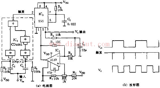
As shown in the figure, the circuit is composed of a differential trigger circuit, a controllable oscillation circuit, and the like. It can generate a 50% duty cycle, double frequency pulse wave with an operating frequency of 500~5000Hz.
In this circuit, IC3 is the input terminal 4 of the 2 or the non-gate circuit, and C3, C4, R2, and R3 form a differential pulse edge detection circuit, which generates a calligraphic negative pulse. IC1, R1, and C1 form a one-shot trigger circuit. IC2 uses BIMOS op amp CA3130 to amplify the pulse wave outputted by IC1 through the low-pass filtered DC level, control the 5th pin of the control terminal of 555, and change the trigger threshold level so that IC1 outputs a pulse ratio of 50% duty cycle.
Motion control sensor is an original part that converts the change of non-electricity (such as speed, pressure) into electric quantity. According to the converted non-electricity, it can be divided into pressure sensor, speed sensor, temperature sensor, etc. It is a measurement, control instrument and Parts and accessories of equipment.
Remote Control Motion Sensor,Photocell And Motion Sensor,Homeseer Motion Sensor,Lutron Motion Sensor Caseta
Changchun Guangxing Sensing Technology Co.LTD , https://www.gx-encoder.com