Multimeters, also known as multiplex tables, multimeters, tri-meters, and multi-use meters, are indispensable measuring instruments for power electronics and other departments. Generally, voltage, current and resistance are the main purposes. The multimeter is divided into a pointer multimeter and a digital multimeter according to the display mode. It is a multi-functional, multi-range measuring instrument. The general multimeter can measure DC current, DC voltage, AC current, AC voltage, resistance and audio level, etc. Some can also measure AC current, capacitance, inductance and semiconductor. Some parameters (such as β) and so on.
How to check the line multimeter usageUse AC voltage or DC voltage as needed. Use electrical blocking to detect circuit paths and shorts without a point!
If the multimeter has a buzzer, use the two meter pens to measure the same wire. If there is a short circuit, there will be no response. If there is a path, there will be a buzzer sound. Sometimes when the device itself is not grounded, the case can be charged. You can use the multimeter red pen to set the black mark on the case. Compared with the direct contact with the ground, the strength of the leakage current of the casing can be measured so that the DC current is measured in the same series of circuits in the remaining working core.
Check the line leakage or not, you must use a megger (shake table), because the multimeter voltage is lower (9v), the megohm meter voltage is higher 500v. Because the line operating voltage is 220v, it is not easy to diagnose the line where the leakage is not obvious. To check the line leakage with a digital meter, you first need to cut off the power supply. After discharging the line, use the resistance file and 2M gear position measurement. The normal display is 1 (infinite).
The measuring line is connected and can be measured with a multimeter ohmmeter. When measuring, you should select the meter pointer to approach the deflection 0 ohm. If the line is in the circuit, connect one end of the line (A end) to the multimeter (red meter) 100 ohm file, and the black meter pen to the other end of the line to be measured (B end). If the measured result is zero, this means The line is connected, also called the path. Only the path, the current is passed through the circuit. If the multimeter ohmmeter pointer of the multimeter is not close to zero ohm, the line is already open. Open circuit or open circuit.
How to find a problem with a multimeterWhen the multimeter is used to check electrical faults, generally only two files are used, one is the voltage file (including the AC and DC voltage files) and the other is the ohm.
If the device is not working, the first thing you think about whether the device voltage is normal, you need to use the multimeter's voltage file (choose AC voltage or DC voltage, depending on whether your device is an AC device or a DC device). If the control loop or the secondary loop is broken, you must use the voltage file to measure whether the voltage at a certain place is normal if you are familiar with the schematic. If it is determined that the voltage at the place should not be there, some of them are not. This indicates that there is a disconnection or poor contact. In order to make more certain whether there is a problem at this point, you have to disconnect the power of the device, and have the ohmmeter of the multimeter to determine whether the line has been disconnected in order to eliminate the fault. In general, it depends mainly on your familiarity with the equipment and the accumulation of experience in the work.
How to check the short circuit with a multimeter?The short-circuit resistance of the capacitor is zero; the resistance of the transformer and the motor coil is also zero;
Short circuit between two insulated coils, etc. Some short circuits are not detected, such as short-circuit between coil turns.
Discussion:
The resistance is non-polar. Use a multimeter to measure the voltage of the electron. The red meter is connected to the positive, the black meter is connected to the negative, the multimeter is displayed as a positive number, and vice versa. It can be determined by the multimeter reading, and the multimeter with a buzzer is hit. Buzzer gear position measurement, if the multimeter emits a drip sound, it is judged to be short-circuited.
Use a multimeter to detect faulty circuits and find faulty componentsToday, I will teach you a simple multimeter to judge whether the component is burned or not.
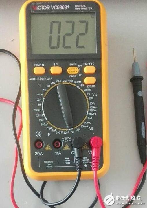
The multimeter we use
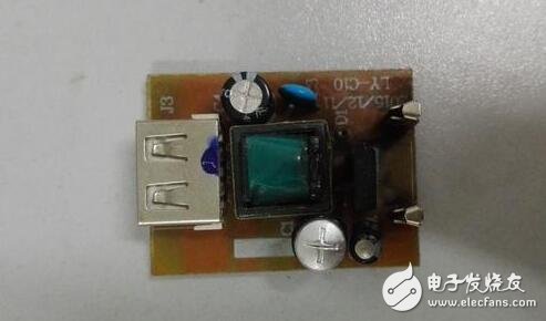
Today, I will use the broken mobile phone charger as an example to explain to you that this broken charger should be too current when working, the solder on the PCB has melted, and some components are directly burned. First look at the picture of the charger that was burned.
Negative
positive
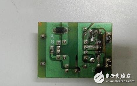
On the opposite side of the picture on the reverse side, we can see that the solder on the PCB is obviously melted. There is no direct way to detect such a problem with the multimeter. This phenomenon is also obvious. It can be seen at a glance. If it is repaired, then it will be The two ends of the melt lead a line and reconnect them together.
In the picture on the front, you can clearly see that the capacitance under the board has obviously been drummed, indicating that it has burned. Of course, we can check it with a multimeter. The right side of the drum has a small capacitor, which seems to be complete. I don't know if it is bad or not, we use a multimeter to measure these two small components.
Capacitance detection
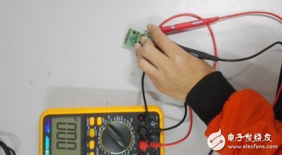
The first step: adjust the multimeter to the capacitor file to select the appropriate range
Step 2: Place the multimeter's test leads at the ends of the two component pins
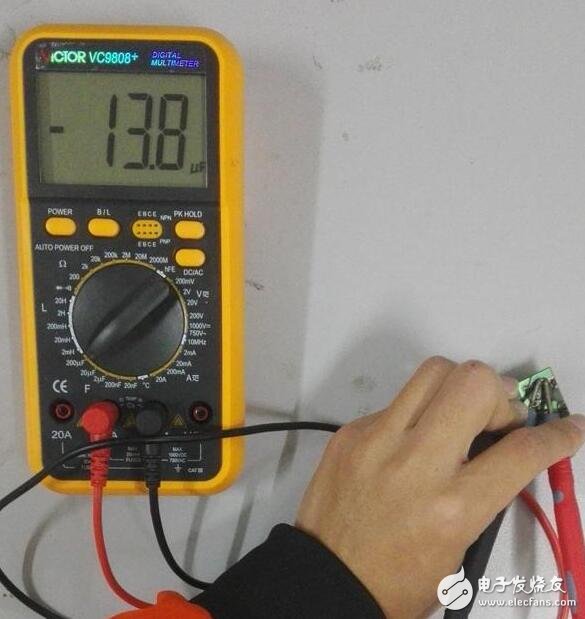
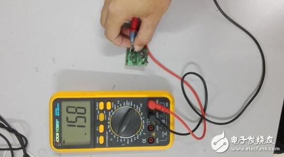
Measure that small capacitor live map
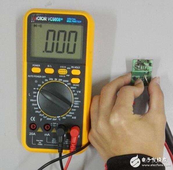
Measuring the capacitance of the drum
After we use the multimeter test, we can clearly see that the small capacitance is measured by the number, read the multimeter to display the number, and then compare the actual value of the capacitor. If the two values ​​are close, then the capacitor is normal. Our capacitor is labeled 10uf, and it is close to measuring 13.8uf.
Looking at the second picture, you can clearly see that the multimeter's display is directly zero, which is enough to show that the drum's capacitance is indeed burned. If you want to fix it, find a parameter with the same capacitance to replace this one. .
Diode detection
After talking about the capacitor, let's talk about the detection of the diode. The diode detection method is a bit simpler than the capacitance detection. Because our multimeter has its own diode block, and there is only one position, regardless of the range problem, we adjust it to the diode block. Then connect the anode of the multimeter to the anode of the diode. The negative pole of the multimeter is connected to the anode of the diode. If you see the indication on the display of the multimeter, then the diode in the circuit is normal (some multimeters will ring), not being breakdown.
Measuring diode measurement
Inductance detection
In the mobile phone charger, the inductance is a very important component. Almost every charger is indispensable. Therefore, we also need to learn a method to detect the inductance. "Inductance" was learned when we were in high school. The inductance is equivalent to short-circuit to DC. This can be done well with the diode block on the multimeter.
We all know that if the diode block red and black test leads are connected directly to a multimeter, it will make a sound, not connected to the sound, and it is also connected to the inductor. Try it, let us pay attention to the buzzer before connecting. In addition to the sound, the multimeter has only one diode symbol in the upper right corner of the display.

Open circuit or no load display
Next we connect the multimeter to the sides of the inductor, and then look at the changes on the display in the upper right corner of the multimeter display.
Short circuit display
Is there another symbol similar to the signal of a mobile phone? It means that the inductance is normal and there is no open circuit. When this happens, you will still hear the buzzer sound. At this time, we can confirm that the inductance is normal. .
MTU High Voltage Generators with MTU Diesel Engine, HV AC Generator
·Engine and alternator shall be mounted on a same frame steel skid.
·Small size, low weight, easy to operating, installation and maintenance.·World most famous brand diesel engine: MTU engine
·World famous brand High Voltage AC alternator: Stamford, Leroy Somer, Marathon, Faraday, etc
·Advanced and reliable controller: Auto start, AMF & Remote control by PC with RS232/485
·Full range protect function and alarm shutdown feature.
·Comply with ISO8528 national standard and ISO9001 quality standard.
. Voltage: 3kV, 3.3kV, 6kV, 6.3kV, 6.6kV, 10kV, 10.5kV, 11kV,13.8kV
Mtu Hv Genset,Mtu Hv Generator,,Mtu High Voltage Genset,Mtu High Voltage Generator
Guangdong Superwatt Power Equipment Co., Ltd , https://www.swtgenset.com