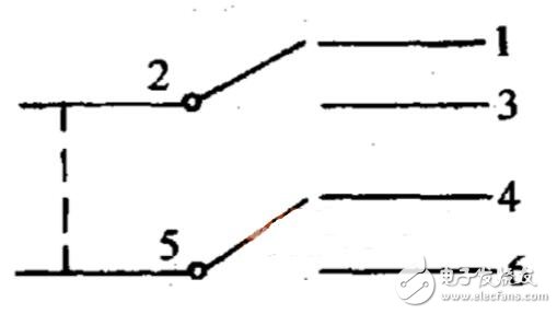
The six-leg switch (six-leg self-locking switch) is also the double-pole double-throw switch. We have 2 pins in total, 3 pins in each row, and the middle is a common one, corresponding to the left and right 2 feet. One normally closed, the other row is the same as this, normally open to normally open, common point to common point, normally closed to normally closed, but completely independent of 2 groups, unless you connect them on the PCB is the pass .
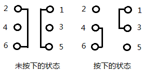
Connection method: public point 1 4 is normally closed 3 6 normally open to see how you want to control if it is a single way to connect 1 2 or 2 3 can be. There are still many answers to the questions one by one.
Six-legged self-locking switch schematic and connectionEach row is a single single-pole double-throw switch, the middle is common, you can use SW-DPDT first as long as it is determined that the middle is public, as to which side is open which is closed, this problem can be left to the welding Time to solve it.
The six-pin self-locking switch is a double-pole double-throw switch. The principle of a lot of data on the Internet is not correct. Here I have drawn a picture. Except for the parts connected by black lines on the figure, the other parts are not connected.
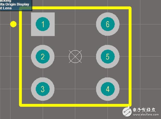
1~2 distance 2.54mm
3~1 distance 5.08mm
Package Name: KFT-7
Small class of knowledge: PCB six-foot button problemI don't know how to connect the six-legged buttons.
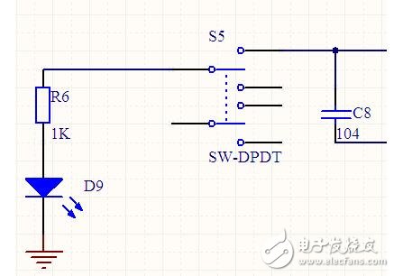
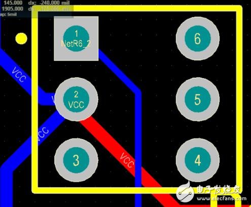
Power switch, schematic and PCB part as shown above, look at the PCB diagram, the switch is normally connected, after the 1-6 pad connection.
answer:
The schematic doesn't matter, it probably shows the meaning.
The key is the packaging of the PCB. Two of the 6-pin switches I have used before are turned on.
The test method is very simple. Take a multimeter and hit it. After the press, the two are turned on, and they are not turned on after disconnection. Then these two pins are the pins you are looking for.
A power cord, line cord, or mains cable is an electrical cable that temporarily connects an appliance to the mains electricity supply via a wall socket or extension cord. The terms are generally used for cables using a power plug to connect to a single-phase alternating current power source at the local line voltage-(generally 100 to 240 volts, depending on the location). The terms power cable, mains lead, flex or kettle lead are also used. A lamp cord (also known as a zip cord) is a light-weight, ungrounded, single-insulated two-wire cord used for small loads such as a table or floor lamp.
Power Cord,Home Appliance Power Cord,Power Cable Cord
Dongguan YAC Electric Co,. LTD. , https://www.yacentercn.com