This paper proposes a design scheme of two-way temperature controller based on 51 single-chip microcomputer. The design scheme uses two DS18B20 temperature sensors to collect the temperature of two different places, which is processed by AT89C51, and the measured temperature is displayed by a four-digit LED digital tube. The two digits are the temperature of the first temperature sensor, and the last two digits are the temperature of the second temperature sensor. 3 buttons are used to set the highest and lowest temperature, and a buzzer and a motor are used to alarm that the temperature is too high or too low.
1 Introduction
At present, the problem of temperature controller is how to reduce cost, reduce power consumption, the accuracy of temperature measurement and the simultaneous display of multi-channel temperature. The realization of the two-way temperature controller based on the C51 single-chip microcomputer is designed in this scheme, which achieves the lowest cost, high accuracy, two-way temperature display and control, and can start the electric fan to cool down when the temperature exceeds the set maximum temperature. When the temperature is lower than the set minimum temperature, the buzzer alarm will be activated, and the user can set the maximum and minimum temperature.
2. System structure
The temperature controller system includes the following main parts: temperature sensor, alarm circuit, LED display circuit, keyboard control, and 89C51 control part. as the picture shows:
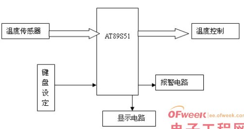
The design and implementation of this system: after starting the temperature controller, the green light is on, the first two digits on the four-digit LED digital display are the ambient temperature measured by temperature sensor 1, and the last two digits are the ambient temperature measured by temperature sensor 2.
3. Hardware structure
3.1 Temperature sensor
This design uses DS18B20 as the temperature sensor. Compared with the traditional thermistor, DS18B20 has the advantages of high accuracy, small measurement error, and convenient multi-point temperature measurement. Therefore, DS18B20 is used as the temperature sensor.
3.2 Alarm circuit
This design adopts buzzer and electric fan alarm circuit. The buzzer alarm circuit is composed of triode and buzzer. When the temperature is lower than the set minimum temperature, the buzzer will alarm. The electric fan alarm circuit is composed of a triode and an electric fan. When the temperature is higher than the set maximum temperature, the electric fan will alarm.
3.3 Display circuit
The system adopts LED digital display tube display, with high LED brightness and high viewing angle. LCD has a low viewing angle, low brightness, and high price. Considering that this temperature sensor is mainly used in greenhouses and other environments with low brightness, LED is selected as the display from an economical and practical point of view.
3.4 Keyboard Control
The system uses 3 independent keys as the keyboard control circuit. Keyboards are generally divided into two types: independent and matrix keyboards. The independent keyboard has a simple structure, but occupies a lot of resources; the matrix keyboard has a more complex structure, but occupies less lines. Considering that the number of keys required in this design is not large, three independent keyboards are used to complete the temperature setting of the two temperature sensors.
3.5 89C51 control part
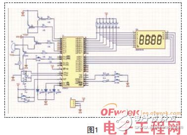
This system uses AT89C51, 51 for small electronic products, and the hardware design circuit is shown in Figure 1.
4. Software Design
The system is implemented using assembly language coding, and the processing time is faster than the program coded in C language.
The main program includes system initialization, keyboard scan selection subroutine, temperature comparison subroutine, temperature measurement subroutine, temperature calculation subroutine, and display subroutine.
4.1 Main program module
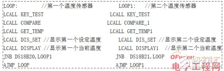
In the main program, initialize the data first, then call the keyboard scanning subroutine KEY_TEST, the temperature comparison subroutine COMPARE, the temperature acquisition subroutine GET_TEMP, the temperature display subroutines DIS_SET and DISPLAY, and then judge the acquisition and display the second temperature The temperature value of the sensor. Write the program as follows:
4.2 LED Display Module
LED display can be divided into two types: dynamic display and static display. Static display occupies more lines. In order to reduce hardware cost, this design adopts the method of dynamic scanning display to display the temperature value of two temperature sensors.
The DISPLAY and DISPLAY1 functions read the temperature of the first and second temperature sensors respectively and display the temperature of the two temperature sensors according to the data of the temporary storage unit. Programming idea: According to the SIGN sign, it is judged to switch to different displays, and the data obtained from the look-up table is stored in different units and displayed on the LED.
4.3 Keyboard Control Module
The keyboard judges and sets the highest or lowest temperature of the first or second temperature sensor by setting the SIGN mark. The programming idea is as follows: the SIGN is initially set to 0, and when the first key is pressed, it is assigned to 1. When it is pressed again, add one, until it is reassigned to 0 when it is pressed for the 5th time, and different settings are determined according to the value of SIGN.
4.4 Temperature Sensor Module
According to the 3 steps that the temperature sensor DS18B20 must go through to complete the temperature conversion, the program: MOV A, #0CCH//Skip ROM MOV A, #44H // Carry out temperature conversion MOV A, #0BEH//Read the contents of the temporary storage memory.
4.5 Alarm Module
When the real-time temperature is higher than the set maximum temperature or the real-time temperature is lower than the set minimum temperature, the single-chip microcomputer will control the buzzer or electric fan to work, and the function to judge whether the current temperature is in the normal range is COMPARE. The high-temperature part of the program is as follows :
5. Simulation test
Before we write programs to DS18B20, we must debug our own programs. But we can't see how the program works. Therefore, we can use the emulator to simulate. Through the emulator, we can see the data sent by DS18B20, the temperature value read out, and the change of the registered value. The system connection diagram is shown in the following figure:
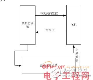
We can now display the temperature collected by the DS18B20 on the PC and display a new line after each temperature value is displayed. The test proves that the system has strong practicability and achieves the predetermined function.
6. Summary
The temperature controller designed in this scheme adopts AT89C51 microcontroller as the core, DS18B20 as the temperature sensor, and realizes the acquisition and display of two-way temperature through four-digit LED display and cyclic scanning. Then, the simulation test confirmed that the modified design scheme is economical and practical, and it can measure the temperature in two places, which can meet the use in different environments such as greenhouses, indoor homes, and industrial control.
Kadena (KDA) is a hybrid blockchain network and smart contract platform that aims to unite public applications, private blockchains, and other interoperable chains in one place, driving traffic to the high-bandwidth computer at the heart of the Kadena public chain. Kadena`s mining algorithm is Blake2S, which supports ASIC mining.
Kadena is a blockchain network and smart contract token aiming to bring together both public applications and private blockchain.
The coin solves various problems that prevent blockchain adoption on a bigger scale. The protocol enables businesses and developers to make transactions and share information across many networks.
The Coin is actually on the grid to reduce users` experience in the network. Ethereum users experience a lot of network congestion which results in high gas fees.
A few changes have come into Kadena mining. A proof of work blockchain uses PACT to create smart contracts in the hidden gen. Therefore you need to know the following before mining Kadena. PACT is an intelligent contract language serving the needs of the blockchain community.
1.You Need an Excellent Mining Hardware
To mine efficiently, you will require suitable mining hardware. Kadena uses ASIC miners. But, unfortunately for Kadena miners, CPUs and GPUs are not usable. Furthermore, ASIC mining receives support from the Blake2S algorithm.
2.Make Sure You Have a Kadena Wallet Address
You will need a Kadena wallet address to receive and monitor your profit. F2pool also makes the distribution of the revenues to every user daily at 2KDA. The Kadena node wallet is a perfect wallet where you can receive your mined KDA. all you need to do is install it, click receive, and have a new wallet address.
You will need to configure your Asic Miner to a mining pool server for your hashrate and profit to be recorded and monitored.
3.Start Mining
After all the setting is done, your miner will be ready to work. Make sure you enter your wallet address and click on the go button to receive your revenue.
Kda Miner,Antminer Ka3 166Th,Bitmain Antminer Ka3 166Th,Antminer Bitmain Ka3
Shenzhen YLHM Technology Co., Ltd. , https://www.sggminer.com