Professor Zhou Ligong's new book, "Programming for Ametal Frameworks and Interfaces (I)", offers an in-depth exploration of the AMetal framework. By reading this book, you can learn advanced software design principles and development ideas focused on interface programming. The goal is to help you concentrate on your core domain, shift your programming mindset, and achieve mutual growth between the company and the individual. Authorized by Professor Zhou Ligong, the Zhiyuan Electronic Public Number will serialize the content of this book, sharing it with everyone.
The seventh chapter is titled "Programming for General-Purpose Interfaces". This chapter covers 7.1 LED Control Interface, 7.2 HC595 Interface, and 7.3 Buzzer Control Interface.
Guide to this Chapter
Although interface-oriented programming is simple and easy to understand, it may not fully leverage application reuse, which contributes to the high cost of software development. Programming for general-purpose interfaces is based on the application design of the AMetal framework. The core of the application is to develop a unified interface specification that allows programmers to focus on their core competencies while reducing constraints from non-core domains.
7.1 LED Control Interface
> > > 7.1.1 LED Universal Interface
To implement cross-platform application software, AMetal provides a common interface for operating LEDs, as detailed in Table 7.1.
Table 7.1 LED Universal Interface (am_led.h)
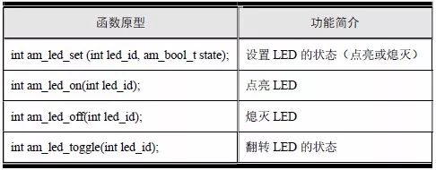
1. Set the status of the LED
The function prototype for setting the LED state is:

Here, led_id represents the LED number. The AM824-Core development board has two LEDs: LED0 and LED1, numbered 0 and 1 respectively. If the LED state value is AM_TRUE, the LED turns on; otherwise, it turns off. The sample program is shown in Listing 7.1.
Listing 7.1 am_led_set() Sample Program

2. Light the LED
The function prototype for lighting the LED is:

Where led_id is the LED number, and the corresponding sample program is detailed in Listing 7.2.
Listing 7.2 am_led_on() Sample Program

3. Turn Off the LED
The function prototype for turning off the LED is:

Where led_id is the LED number, and the corresponding sample program is detailed in Listing 7.3.
Listing 7.3 am_led_off() Sample Program

4. Toggle the LED Status
Toggling the LED status means changing it from on to off or from off to on.
Its function prototype is:

Where led_id is the LED number, and the corresponding sample program is shown in Listing 7.4.
Listing 7.4 am_led_toggle() Sample Program
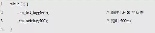
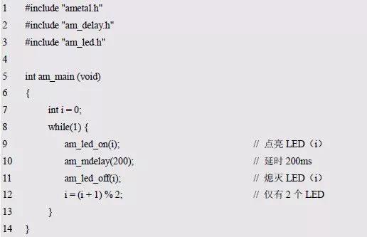
The two LEDs on the AM824-Core are controlled by the LED universal interface to alternate illumination (the effect of the two LEDs). The corresponding example is shown in Listing 7.5.
Listing 7.5 Two LEDs Alternately Lit (LED Street Light)
> > > 7.1.2 LED Driver
If you want to operate LEDs using the universal interface, you must provide the appropriate drivers for specific LED devices. Based on this, AMetal provides the corresponding driver initialization function. When you initialize an LED instance with this function, you can operate the LED using the generic LED interface. Its function prototype is:

P_dev is a pointer to an instance of type am_led_gpio_dev_t;
P_info is a pointer to the instance information of the am_led_gpio_info_t type.
Instance
The definition of the am_led_gpio_dev_t type (am_led_gpio.h) is as follows:

Where g_led_gpio is a user-defined instance whose address is passed as an argument to p_dev.
2. Instance Information
The example information mainly describes the LED-related information, such as the GPIO pin number used, whether the LED is low-level active, and other details. The definition of its type am_led_gpio_info_t (am_key_gpio.h) is as follows:
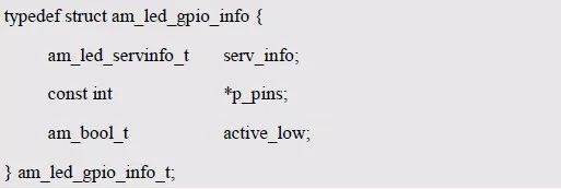
(1) serv_inf0
Serv_info contains LED number information, and its type am_led_servinfo_t is defined as follows:
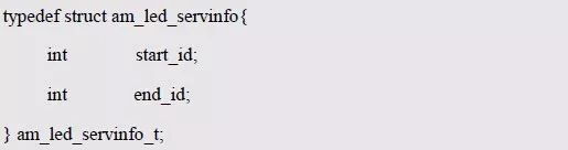
An LED device may contain multiple LEDs, start_id is the starting number of the LED, end_id is the ending number of the LED, and the number of LEDs is end_id–start_id+1. Since the AM824-Core development board has only two LEDs, LED0 and LED1, its start number is 0 and the end number is 1.
(2) p_pins
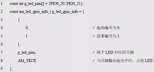
P_pins points to an array that stores the corresponding pin numbers of the LEDs. For example, LED0 of the AM824-Core development board is connected to PIO0_20 of the MCU through J9, and LED1 is connected to PIO0_21 of the MCU through J10. Based on this, define an array that holds the pin numbers, such as:

The address of this array is the value of p_pins.
(3) active_low
When the pin outputs a low level, the LED is lit, so the value of active_low is AM_TRUE. The instance information is defined as follows:
The initialization of the LED is done based on the instance and instance information. Such as:

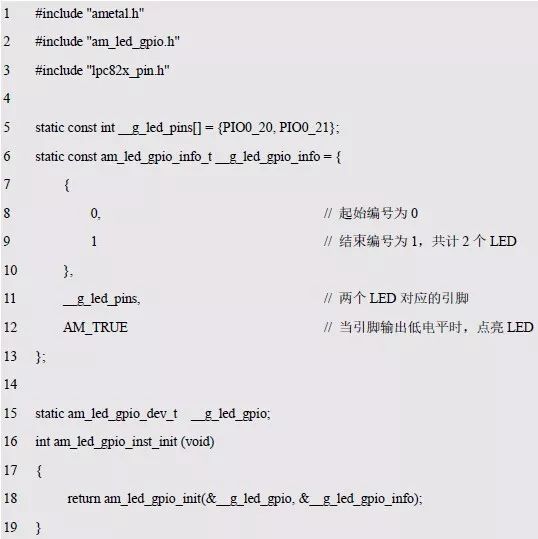
When the initialization is complete, the general LED interface can be called to operate LED0 and LED1. In order to facilitate the configuration of LEDs (modification of instance information), based on the modular programming idea, the definitions of initialization related instances and instance information are stored in the LED configuration file, and the instance initialization function interface, source file and header file program examples are extracted through the header file. See Listing 7.6 and Program Listing 7.7 for details.
Listing 7.6 LED Instance Initialization Function Implementation (am_hwconf_led_gpio.c)
Listing 7.7 LED Instance Initialization Function Declaration (am_hwconf_led_gpio.h)

Subsequent only need to use the parameterless instance initialization function to complete the initialization of the LED instance:

The AM0-Core’s LED0 and LED1 are an on-board resource that is initialized by default at system startup, so the application can use LED0 and LED1 directly without having to call the instance initialization function.
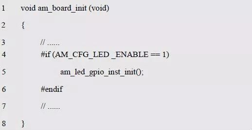
If the user does not need to use the LED, in order to save memory space, you can modify the AM_CFG_LED_ENABLE macro value in the project configuration file (am_prj_config.h) to 0, and cut off the LED program, which essentially controls a program in the board-level initialization function. See program list 7.8 for details.
Listing 7.8 Principle of cropping LEDs in board level initialization
> > > 7.1.3 MiniPort-LED
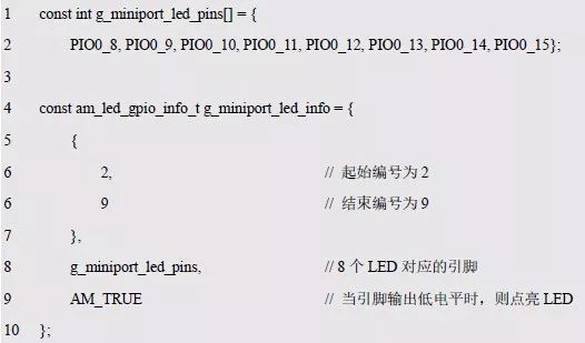
The MiniPort-LED module consists of 8 LEDs. When the MiniPort-LED is connected to PIO0_8~PIO0_15 of AM824-Core, if the GPIO output is low, the LED is lit. Since the MiniPort-LED is also a GPIO-driven LED, the same LED driver as the on-board LED can be used. Its examples are defined as follows:

To avoid conflict with the onboard LED number, the Miniport-LED should use a different number than the onboard LED, for example, the number is defined as 2~9. If the system does not use onboard LED0 and LED1 (the AM_CFG_LED_ENABLE macro value in the project configuration file has been changed to 0), only the MiniPort-LED is used, the number is defined as 0~7. Its instance information is defined as follows:
The initialization of the Miniport-LED can be done based on the instance and instance information. Such as:

When the initialization is completed, the general LED interface can be called to operate LED2~LED9. In order to facilitate configuration (modification of instance information) Miniport-LED, based on the modular programming idea, the definitions of initialization related instances and instance information are stored in the configuration file of Miniport-LED, and the instance initialization function interface, source file and The program examples for the header files are detailed in Listing 7.9 and Listing 7.10, respectively.
Listing 7.9 Miniport-LED instance initialization function implementation (am_hwconf_miniport_led.c)
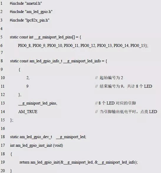
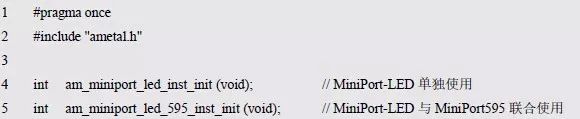
Listing 7.10 MiniPort-LED Instance Initialization Function Declaration (am_hwconf_miniport_led.h)

Subsequent initialization of the Miniport-LED instance is only possible using the parameterless instance initialization function:

When the initialization is complete, LED2~LED9 can be operated using the general LED interface. In the AM824-Core, the MiniPort-LED is an optional board resource that does not perform initialization as default on-board LED0 and LED1. If you are using a MiniPort-LED, you must call the MiniPort-LED instance initialization function.
7.2 HC595 Interface
> > > 7.2.1 HC595 Universal Interface
AMetal provides a common interface for operating the HC595, as detailed in Table 7.2.
Table 7.2 HC595 Universal Interface (am_hc595.h)
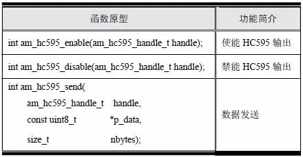
1. HC595 Output
The function prototype that enables the HC595 output is:

Among them, the handle is the instance handle of HC595, which can be obtained by the specific HC595 driver initialization function. Its type am_hc595_handle_t(am_hc595.h) is defined as follows:

When not enabled, the output of the HC595 is in a high-impedance state. After it is enabled, it can output 0 or 1 normally. For the sample program, see Listing 7.11.
Listing 7.11 am_hc595_enable() Sample Program

Among them, hc595_handle can be obtained by the specific HC595 driver. If the HC595 is driven by SPI, it can be obtained by the following statement:

The instance initialization function am_miniport_595_inst_init() will be described in detail later.
2. Disable HC595 Output
After the disable, the HC595 output is in a high-impedance state, and its function prototype is:

Among them, handle is the instance handle of HC595, the sample program is shown in Listing 7.12.
Listing 7.12 am_hc595_disable() Sample Program

3. Output Data
The function prototype for the output data is:

Where handle is the instance handle of HC595, p_data is the buffer pointing to the data to be output, and nbytes specifies the number of bytes of the output data. For a single HC595, it can only output 8-bit data in parallel, that is, it can only output single-byte data. The sample program is detailed in Listing 7.13.
Listing 7.13 Sample program for outputting single-byte data

When more than 8 bits of data need to be output in parallel, multiple HC595 cascades can be used, and multi-byte data can be output at this time. The sample program is shown in Listing 7.14.
Listing 7.14 Sample program for outputting multibyte data

For the MiniPort-HC595, only one HC595 is included, so only 1 byte of data can be output at a time.
> > > 7.2.2 HC595 Drive
AMetal already provides a driver for the SPI-based HC595, which provides an initialization function that, when initialized with an HC595 instance, yields a generic HC595 instance handle. Its function prototype is:

P_dev is a pointer to an instance of type am_hc595_spi_dev_t;
P_info is a pointer to the instance information of the am_hc595_spi_info_t type.
Instance
An example of defining the am_hc595_spi_dev_t type (am_hc595_spi.h) is as follows:

Where g_miniport_595 is a user-defined instance whose address is passed as an argument to p_dev.
2. Instance Information
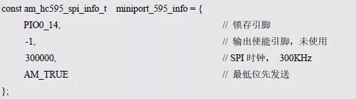
The example information mainly describes the information about the HC595, such as the latch pin, the output enable pin, and the SPI rate. The definition of the type am_hc595_spi_info_t (am_hc595_spi.h) is as follows:

Among them, pin_lock specifies the latch pin of HC595, which is STR pin. The pin connected to LPC824 is PIO0_14, so the value of pin_lock should be set to PIO0_14.
Pin_oe specifies the output enable pin of the HC595, which is not connected to the LPC824 and is fixed low, so the value of pin_oe should be set to -1.
Clk_speed specifies the speed of the SPI, which can be set according to actual needs. If the output of the HC595 is used to drive devices such as LEDs or digital tubes, the rate requirement is not high and can be set to 300000 (300KHz).
Lsb_first determines the order of the output bits when an 8-bit data is output. If the value is AM_TRUE, it indicates that the lowest bit is output first, and the highest bit is output. If the value is AM_FALSE, it indicates the lowest bit and the output, the highest bit first. Output, the first output bit determines the level of Q7 at the HC595 output, and the last output bit determines the level of Q0 at the HC595 output. If set to AM_TRUE, when the subsequent discovery output order is opposite to the order of the expected output, the value can be modified to AM_FALSE. Based on the above information, the instance information can be defined as follows:
3. SPI Handle Handle
If the HC595 output is driven by the SPI0 of the LPC824, the SPI handle is obtained by the SPI0 instance initialization function am_lpc82x_spi0_inst_init() of the LPC82x. Which is:

The SPI handle can be passed directly as an argument to the handle.
3. Example Handle
The return value of the HC595 initialization function am_hc595_spi_init () is the handle of the HC595 instance, which is the actual argument of the first parameter (handle) of the HC595 general interface. Its type am_hc595_handle_t(am_hc595.h) is defined as follows:

If the return value is NULL, the initialization fails; if the return value is not NULL, the valid handle is returned.
Based on the modular programming idea, the definitions of the initialization related instances and instance information are stored in the corresponding configuration file, and the instance initialization function interface is extracted by the header file. The program examples of the source file and the header file are respectively shown in the program list 7.15 and the program list. 7.16.
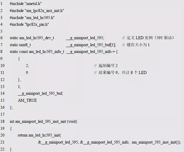
Listing 7.15 Example Initialization Function Sample Program (am_hwconf_miniport_595.c)
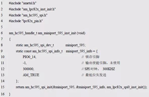
Listing 7.16 Instance Initialization Function Interface (am_hwconf_miniport_595.h)

Subsequent only need to use the parameterless instance initialization function to get the instance handle of HC595:

When directly connected to the MiniPort-LED using the AM824-Core, 8 GPIOs are used to control 8 LEDs, thanks to the flexibility of the MiniPort interface. When the GPIO resources are insufficient, you can add the MiniPort-595 between the AM824-Core and the MiniPort-LED, and use the output of the 595 to control the LEDs to save the pins.
When the MiniPort-595 and MiniPort-LED are connected, the equivalent schematic is shown in Figure 7.1.
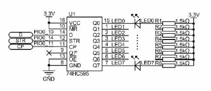
Figure 7.1 MiniPort-595+MiniPort-LED
By controlling the output of the HC595, the effect of controlling the LED to turn on and off can be achieved. See Appendix 7.17 for an example.
Listing 7.17 Sample program for the 74HC595 driver LED
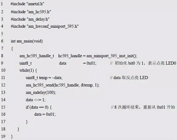
It can be seen that the advantage of the universal interface is to shield the underlying differences, so that regardless of how the underlying hardware changes, the application can use the same set of interfaces to operate the LED. Obviously, whether you use the GPIO to directly drive the MiniPort-LED or the HC595 to drive the MiniPort-LED, you can access it using standard interfaces for the user. AMeatl provides a driver that uses the HC595 control LED. Once the initialization of the corresponding instance is completed using the initialization function, the LED can be operated using the general purpose interface.
> > > 7.2.3 Using the HC595 to Drive the LED
AMetal has provided a driver that uses the HC595 to control the LEDs. This driver provides an initialization function that can be used to operate the LEDs using the generic LED interface after initializing an LED instance. Its function prototype is:

P_dev is a pointer to an instance of type am_led_hc595_dev_t;
P_info is a pointer to the instance information of the am_led_hc595_info_t type.
Instance
An example of defining the am_led_hc595_dev_t type (am_led_hc595.h) is as follows:

Where g_miniport_led_595 is a user-defined instance whose address is passed as an argument to p_dev.
2. Instance Information
The example information mainly describes the information about the LED driver LED, such as whether the LED is lit low, the corresponding LED number and other information. The definition of its type am_led_hc595_info_t (am_led_hc595.h) is as follows:

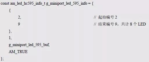
(1) serv_info
Serv_info contains the number information of the general interface access LED. When using the HC595 driver, the number information can remain unchanged, also 2~9.
(2) hc595_num
Hc595_num indicates the number of HC595s. Obviously, one HC595 can only output 8 bits of data, so it can control up to 8 LEDs. When there are more than 8 LEDs to be controlled, multiple HC595 cascades are required. For the MiniPort-LED, which has only 8 LEDs, just one HC595 is used to control 8 LEDs, so the value of hc595_num should be set to 1.
(3) p_buf
P_buf is a pointer to a buffer of size hc595_num that is used to cache the current output value of each 595. Since the value of hc595_num is set to 1, the size of the cache is also 1, and the cache is defined as follows:

Among them, g_miniport_led_595_buf is the cached first address, which can be used as the value of p_buf.
Based on the above information, the instance information is defined as follows:
3. HC595 Handle Handle
If you use the output of the Miniport-595 to control the MiniPort-LED, you should obtain the handle of the HC595 through the instance initialization function am_miniport_595_inst_init() of the MiniPort-595. Which is:

The HC595 handle can be passed directly as an argument to the handle. The initialization of the LED instance can be done based on the instance, instance information, and HC595 handle:

Since the HC595 is another way to drive LEDs, add it to the am_hwconf_miniport_led.c file. For ease of use, add the declaration of the instance initialization function to the am_hwconf_miniport_led.h file, as described in Listing 7.18 and Listing 7.19.
Listing 7.18 Example Initialization Function Sample Program (am_hwconf_miniport_led.c)
Listing 7.19 am_hwconf_miniport_led.h file update
Subsequent initialization of the Miniport-LED instance is only possible using the parameterless instance initialization function:

When the initialization is completed, the general LED interface operation LED~LED9 can be called. MiniPort-LED has two driving modes: GPIO driver and HC595 driver. When using MiniPort-LED, you should select the corresponding instance initialization function according to the actual situation. But no matter what kind of driving method, after the initialization is completed, for the application, the general LED interface operation LED2~LED9 is called.
7.3 Buzzer Control Interface
> > > 7.3.1 Buzzer Universal Interface
In order to implement application software across platforms, AMetal provides a common interface for operating buzzers, as detailed in Table 7.3.
Table 7.3 Buzzer Universal Interface (am_buzzer.h)
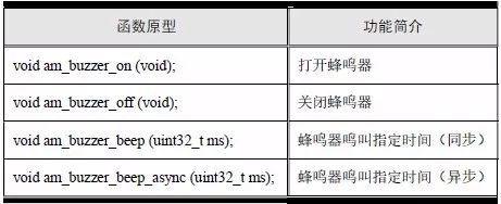
1. Turn On the Buzzer
The function prototype for turning on the buzzer is:

The sample program for turning on the buzzer to make the buzzer start to beeping is shown in Listing 7.20.
Listing 7.20 am_buzzer_on() Sample Program

2. Turn Off the Buzzer
The function prototype for turning off the buzzer is:

See Appendix 7.21 for an example procedure for turning off the buzzer and stopping the buzzer.
Listing 7.21 am_buzzer_off() Sample Program

3. The Buzzer Sounds the Specified Time (Synchronous)
This function is used to turn on the buzzer to automatically turn off the buzzer after a specified time. This function will wait until the buzzer is finished and then return. Its function prototype is:

A sample program that causes the buzzer to sound for 50 milliseconds ("click") is detailed in Listing 7.22.
Listing 7.22 am_buzzer_beep() Sample Program

Note that since the function will wait until the buzzer wakes up, it will return, so the main program will block for 50ms after calling this function.
4. Buzzer Beep for the Specified Time (Asynchronous)
This function is used to turn on the buzzer to make the buzzer automatically turn off after a specified time. Unlike the am_buzzer_beep() function, the function will return immediately without waiting for the buzzer to end. Its function prototype is:

Timer,Electronic Timer, Waterproof Timer, Countdown Timer
NINGBO COWELL ELECTRONICS & TECHNOLOGY CO., LTD , https://www.cowellsocket.com