Application Design of Relay Mode in OFDMA System
The relay technology can enhance the coverage of the original base station. At the same time, 0FDMA technology is the main multiple access method for next-generation mobile communications. Therefore, it is of great practical significance to study and design a relay solution under the constraints of OFDMA technology. Based on the LTE physical layer frame structure, an in-depth analysis of the relay implementation of the 0FDMA modulation system is carried out. Combining the flexible time-frequency resource allocation characteristics of the OFDMA system, a multi-hop / single-hop resource allocation method for 0FDMA is proposed. Finally, An implementation scheme of OFDM relay for FDD mode is proposed. The traditional concept that the relay can only be used for the TDD system has been advanced.
Keywords: LTE; OFDMA; relay; FDD
0 Introduction NGMN (Next Generation Mobile Network Organization) first takes the introduction of (Wireless Board Bandwidth, wBB) as an important goal. The wireless access point AP is a key product to achieve this goal. The AP achieves mobile broadband data well Solution TCO is optimized.
In the NGMN network, the 3GPP air interface long-term evolution LTE project is the most important wireless access technology. The main goal is to provide a high-speed, low-latency, and packet (IP) wireless access network. Naturally, LTE-based APs will be the most important form of base station for wireless broadband access in NGMN deployments. Among the key technologies of the physical layer of the LTE air interface, it supports FDD / TDD duplex mode, and supports OFDMA for resource allocation and user differentiation.
The relay technology can enhance the coverage of the original base station, especially the AP type base station, and effectively improve the throughput of the area, especially the cell edge. Therefore, it is of great practical significance to study and design the relay scheme under the constraints of LTE / OFDMA technology.
This article first briefly introduces the LTE physical layer frame structure, and then gives the air interface resource allocation method after the introduction of 0FDMA system relay; finally, a solution for FDD mode 0FDMA relay implementation is proposed. The traditional concept of the TDD system has been expanded at the forefront.
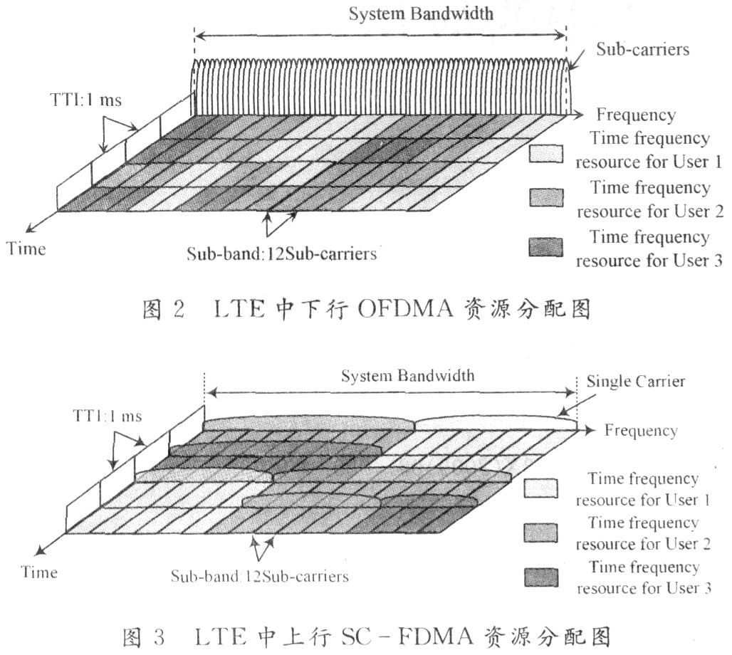
l LTE frame structure 0FDMA, as the most important and promising access scheme in the coming years, allows a wide frequency bandwidth to be split into small segments to serve different terminals. At present, systems such as LTE / UMB and WiMAX use OFDMA as the basic modulation technology of the physical layer of the air interface.
Figure 1 shows the basic frame structure of LTE, suitable for both FDD and TDD modes. The basic frame length is 10 ms, which is divided into 20 0.5 ms subframes, and the two subframes form a 1 ms TTI. In FDD mode, 20 subframes are used for uplink and downlink respectively; in TDD mode, the ratio of uplink and downlink can be configured (# 0/5 subframe is used for downlink).
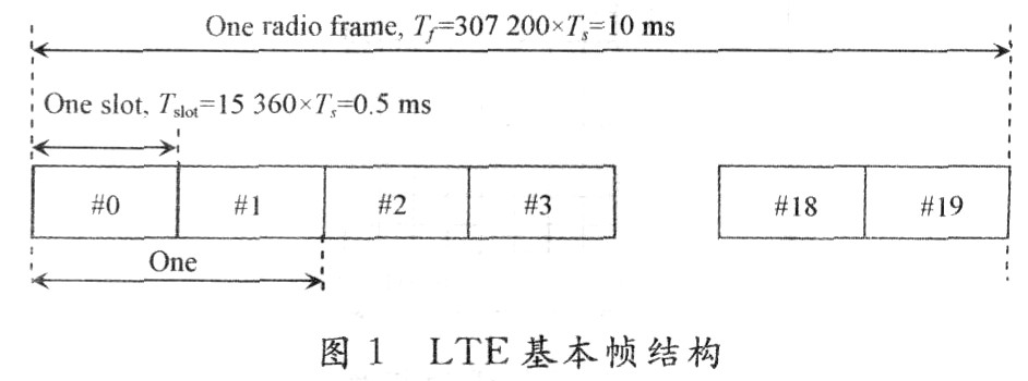
Under the basic frame structure, when the short CP mode is used, the downlink / uplink 7 OFDM / SC-FDMA symbols per subframe; when the long CP mode is used to overcome the larger multipath delay, the downlink / uplink supports each subframe 6 OFDM / SC-FDMA symbols.
In the air interface resource representation of LTE, NDLBW indicates the downlink bandwidth configuration, expressed by the number of downlink subcarriers; NULBW indicates the uplink bandwidth configuration, expressed by the number of uplink virtual subcarriers; NDLsymb indicates the number of 0FDM symbols in a downlink time slot (subframe) ; NULsymb represents the number of SC-OFDM symbols in an upstream slot; NRBBW represents the number of frequency domain resource blocks (with 12 subcarriers as the basic unit).
FIG. 4 is a schematic diagram of a downlink resource grid based on OFDMA in LTE. A resource block based on user scheduling is defined as: the product NDLsymb × NRBBW of the number of consecutive OFDM symbols in the time domain and the continuous subcarrier blocks in the frequency domain. In uplink resource scheduling, a resource block is defined as a subframe and parameters NTX and k0. These two parameters determine the transmission bandwidth and frequency hopping mode. NTX also takes 12 virtual subcarriers as a unit.

It can be seen that LTE can distinguish users in the time domain and the frequency domain. Therefore, the following relay design based on OFDMA can be directly applied in LTE.
2 OFDMA-based relay scheme
2.1 Multi-hop / single-hop resource allocation method based on OFDMA Starting from the difference between single-hop and multi-hop connections, OFDMA technology can be used to split the available frequency band into two parts: one part for single-hop communication and the other part for Multi-hop communication. It is foreseeable that adjacent subcarriers are allocated to multi-hop and single-hop traffic respectively, resulting in two adjacent sub-bands, one for multi-hop and one for single-hop. This means that the air interface of the target system uses a complete frequency band, such as 100 MHz, and splits the entire frequency band into two parts. As an example, FIG. 5 shows the allocation pattern of Nc subcarriers in the OFDM-based air interface. The MH area indicates that this part of subcarriers is used for multi-hop communication, and the SH area indicates that this part of subcarriers is used for single-hop communication.
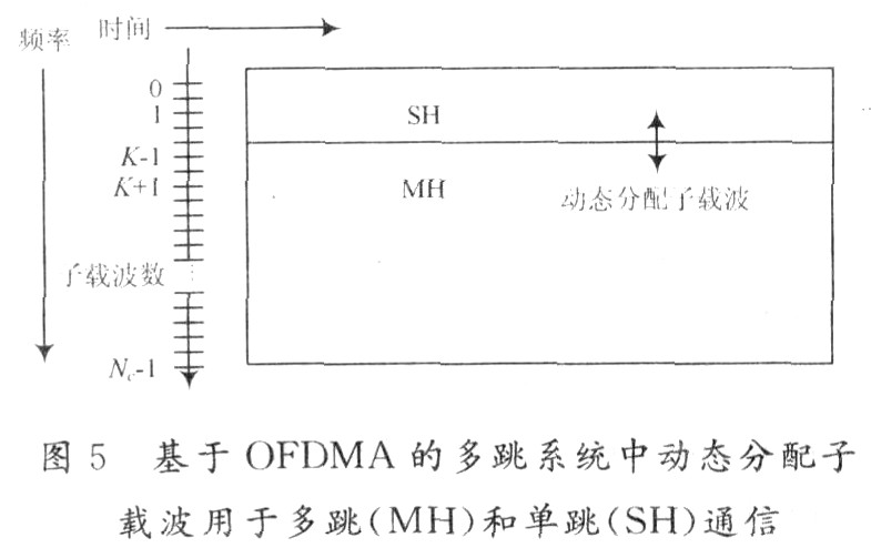
By utilizing the characteristics of OFDMA, the two sub-bands are dynamically segmented in a flexible manner. OFDMA allows different subcarriers to be allocated to different users to form different connections. It is recommended to allocate the sub-carriers into two sub-bands as needed. For example, the sub-carriers in the higher frequency band are allocated to the multi-hop sub-band, and the remaining sub-carriers are used for single hop. The number of sub-carriers allocated to single-hop and multi-hop can be dynamically adjusted according to demand.
Depending on the frequency resource requirements of single-hop and multi-hop traffic, the sub-band division will change, for example, if there is a heavy local traffic between terminals in a multi-hop fixed relay station area, but only a little The bandwidth requirement is used to transmit data with the Internet, so that the multi-hop sub-band will be reduced to a very small number of sub-carriers. However, if multiple hops require more bandwidth, some carriers used for single hops will be allocated to the multi-hop frequency band. For example, if each mobile node has a connection to the Internet, the multi-hop sub-band will be increased to support the large traffic demand relayed through the fixed trunk network.
Between the AP / relay station and the mobile node, and between the AP and the relay station, the uplink / downlink segmentation is generally achieved by means of TDD. However, FDD can also be implemented with this concept on a single-hop link, and a hybrid FDD method can be used for multi-hop connections. Relatively speaking, the multi-hop implementation of FDD is more complicated than that of TDD, especially the hardware solution. This section takes TDD as an example to discuss.
In Fig. 6, through the deployment based on two fixed relay stations, the concept that the subcarriers are dynamically allocated to multi-hop and single-hop traffic is simulated. In this scenario, up to three hops are supported. The first two hops are realized by the multi-hop sub-band between the AP and the two fixed relay stations, and the third hop between the relay station 2 and the MN3 (mobile node 3) is realized by the single-hop band 3 (SH3). In Figure 6, under this topology, different bandwidth allocations are marked. The MH1 frequency band is used for bidirectional multi-hop traffic between AP and FMHNl (SHCommunicaTIon and MHCommLmicaTIon over Fixed Relay StaTIons, here refers to fixed relay stations), and shares subcarriers with single-hop traffic in the SHl area, and mobile nodes in the SHl area are directly AP service. Multi-hop and single-hop traffic in the MH2 area and the SH2 area also share subcarriers in a dynamic manner. In the SH3 area, traffic will monopolize all subcarriers because there are no more multi-hop connections.
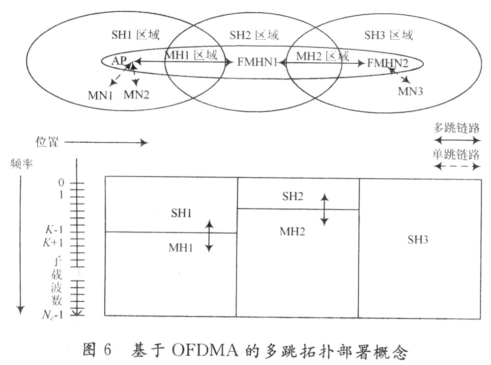
2.2 The design of the sub-band bandwidth in MS-OFDMA because the downlink traffic from the AP to the mobile node is distributed to the single-hop area, and the uplink traffic from the mobile node to the AP is aggregated, which leads to multi-hop Connection, the bandwidth requirements towards AP and Internet are gradually increasing. This is taken into account by allocating a higher number of subcarriers to the MH link near the AP, such as the MH1 link in Figure 6. However, other different subcarrier allocation methods are also possible. For example, when heavy local traffic or large traffic is transmitted through relay stations instead of APs between single-hop areas, MH1 will allocate fewer subcarriers than MH2.
Since we expect traffic on the MH link to be implemented in a LOS environment through a high-gain antenna, the data rate per unit spectrum is much higher than the last hop link between AP / FMHN and MN under the same bandwidth conditions; therefore, If it is assumed that all traffic comes from / to the AP and the Internet, the number of carriers allocated to a multi-hop link can be less than that required on a single-hop link. In addition, the mobile node served by the last relay, such as MN3, will experience the highest number of hops to reach the Internet. The maximum allocated bandwidth for these mobile nodes, such as the SH3 area, partially compensates for this shortcoming, and to a certain extent reduces the delay experienced by different links.
On the other hand, the cell size needs to be appropriately selected. Compared with the cell served by FMHN, the last cell (SH3 area) will become the largest cell (covering more mobile nodes). This kind of cell planning can ensure that each user has a constant data rate in the entire deployment area, which is a research goal of the deployment scheme in the future mobile communication system.
It can be seen that with the help of a novel solution, flexible resource allocation on the end-to-end connection becomes possible. The multi-hop scheme based on OFDMA introduces a logical division method of multi-hop traffic and single-hop traffic, which will serve it through different protocols based on the common physical layer and shared common frequency bands. Compared with single-hop communication, multi-hop communication has different requirements in protocol design, and can develop and deploy effective protocols to independently target different problem areas. At the same time, just like the conventional solution, there is no special requirement for dividing the frequency, only one frequency band is needed. At the same time, there is no need for guard bands similar to those in conventional FDMA between single-hop and multi-hop frequency bands, because OFDMA allows for closer division and subcarriers are orthogonal in the frequency domain.
3 Preliminary discussion of FDD relay solution At present, although the relay technology is used in FDD mode, the hardware implementation is relatively complicated and the cost is relatively high, but FDD is by far the largest mobile communication mode carrying traffic, and FDD mode also takes up the most frequency band The coverage capacity of the frequency band is also the most superior. Therefore, the combined application of FDD mode and relay technology is very necessary. The two-hop mode based on FDD and the logical architecture of the base transceiver station are discussed below.
In the FDD communication mode, the uplink and downlink communication frequency bands are physically divided, and uplink and downlink communication can be simultaneously performed between the base station and the terminal, that is, they can be simultaneously received and transmitted. The upstream occupied frequency band is at a low position, denoted by LB, and the center frequency is defined as fLB; the downstream occupied frequency band is at a high position, expressed by HB, and the center frequency is defined as fHB; the duplex interval between the two frequency bands is up to tens of MHz fDup.
In order to save costs, it is assumed here that the relay station has only one transceiver, that is, it can only receive and transmit one signal at a time. Because the relay station needs to support the four modes of BR / RB / RM / MR (base station sending relay receiving / relay sending base station receiving / relay sending terminal receiving / terminal sending relay receiving), it needs to be through time division The transceiver resources of the relay station are scheduled and divided into two transmission and reception states, BR / RB and RM / MR, in the time domain.
Based on the basic method of MS-OFDMA, the LB and HB frequency bands are subdivided into SH and MH sub-bands for single-hop and multi-hop communications, respectively. MHl / SHl is the frequency band division that the base station and the relay station and the base station and the terminal communicate directly with each other; because the relay station communicates with the base station and the terminal separately in a time-division manner, that is, MH1 is not always occupied for transmission, it is maintained in the relay station coverage area and the base station direct coverage area In the case of good isolation, the single-hop communication SH2 of the relay station can use all frequency bands, otherwise the same frequency band as MH1 is used. It is assumed here that SH2 can use all frequency bands, because the original intention of the relay station is to make up for the coverage hole of the base station. The above frequency allocation pattern is shown in FIG. 7.

In this way, the communication time slot table of this two-hop system is obtained, as shown in Table 1. It can be seen from Table 1 that the relay station acts as a base station and a terminal at different times. This requires that the relay transmitter supports the transmission of two sub-bands of SH (HB) 2 and MH (LB) 1 in a time-sharing manner, and the receiver supports the two sub-bands of MH (HB) 1 and SH (LB) 2 in a time-sharing manner. Frequency band reception.
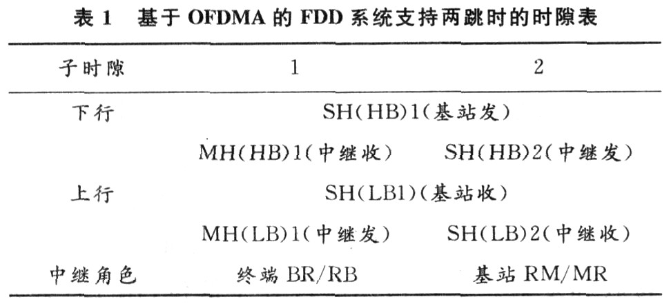
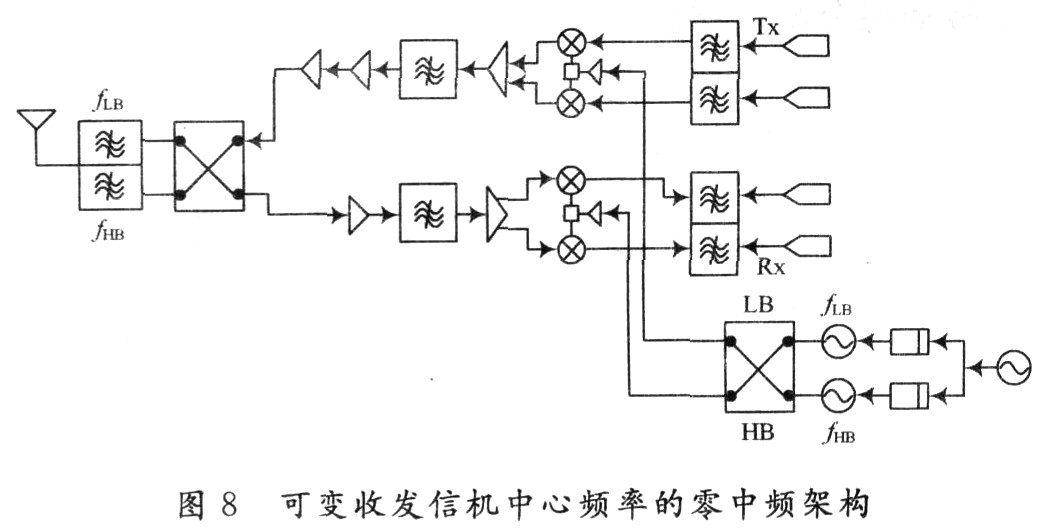
This requires designing a transceiver with a variable center frequency. Figure 8 is a transceiver architecture based on a zero-IF architecture. The two switch matrices support the variable center frequency of the transceiver and the change of the duplexer filter transceiver mode. In this architecture, at subslot 1, fLB is switched to the transmitter PLL, fHB is switched to the receiver PLL, and the RF front-end transmit channel is switched to a filter that supports fLB, and the receive channel is switched to Support fHB filter. At subslot 2, fHB is switched to the transmitter PLL, fLB is switched to the receiver PLL, and the RF front-end transmit channel is switched to a filter that supports fHB, and the receive channel is switched to a filter that supports fLB Device. Then cycle in 2 cycles.
4 Conclusion Based on the OFDMA system, the relay air interface can adopt a more flexible and dynamic time-frequency resource allocation mode, which will become one of the key factors for the relay to commercialization in the OFDMA system, and the FDD-based relay system is also necessary Will become a priority in this commercial process.
Air Fryer,Air Fryers,6L Air Fryer,Commercial Air Fryer
Ningbo Anbo United Electric Appliance Co.,ltd , https://www.airfryerfactory.com