The MAX8678 integrates a charge pump that can drive four white LEDs, each with a dimming range from 24mA to O.lmA. The MAX8678 also integrates a 1.1W Class AB audio amplifier with a soft-start to limit inrush current while providing open and short-circuit protection and thermal shutdown protection. The MAX8678 is specifically designed for portable consumer electronics such as smartphones, camcorders, PDAs, and digital camcorders.
Basic structure and application circuit
The MAX8678 is available in a 16-pin 3mm x 3mm thin OFN package with pinouts and pinouts as shown below.
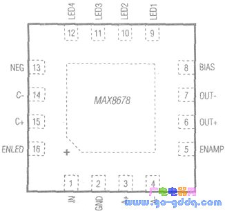
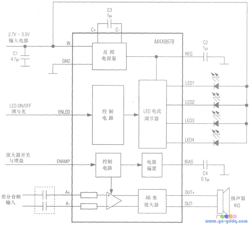
The MAX8678 integrates a charge pump, LED on/off control and LED current regulation circuitry, a mono Class AB audio amplifier, and its on/off and gain control circuitry. Its internal architecture and typical application circuitry are shown below. The MAX8678 pin IN has a supply voltage of 2.7 to 5.5V, and pins LED1 to LED4 drive four white LEDs. The differential audio signal drives the 8Ω speaker from the pin A+ and A- inputs of the MAX8678, and the BTL output on pins OUT+ and OUT-. The Class AB amplifier provides 1.1W of continuous power at a supply voltage of 5V.
Function and working principle
1. High-efficiency white LED charge pump The charge pump of MAX8678 provides constant current for backlight display or camera flash. It can drive 4 white LEDs. When the power supply voltage can fully drive the LED, the adaptive charge pump is turned off to minimize the supply current. And the LED current is linearly adjusted; when the supply voltage is insufficient to drive the external LED at the set current, the charge pump is enabled, a negative voltage is generated on the pin NEG, and the LED output is allowed to maintain the current set by the LED. The end is pulled below ground level.
The MAX8678 generates a PWM signal for higher resolution at lower currents. When the LED current is less than 6.4mA, the MAX8678 regulates the LED current and uses the PWM signal to control the duty cycle. The PWM dimming signal frequency is set at 1 kHz to provide a minimum duty cycle of 1/16 to prevent the LED from affecting the flicker of the human eye. The current ILED and the corresponding duty cycle are given in the table below. 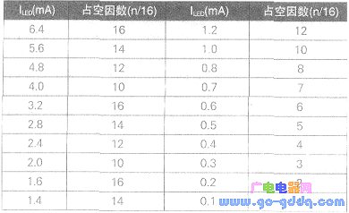
The MAX8678's LED driver provides a low power shutdown mode. After the voltage on the IC pin ENLED is pulled low for 3.2ms, the device enters the shutdown mode, and both the charge pump and the LED current driver are turned off.
The soft-start feature prevents input current overshoot when the MAX8678 is initially powered up or from a semi-closed mode.
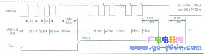
The MAX8678 includes a serial pulse interface to perform on/off control and dimming. The dimming range is pseudo-logarithmic (pseudeo-logarithmic), ranging from 24 mA to O.lmA, with a total of 31 levels. When the pin ENLED is high, the IC turns on and the internal register is set to 24mA. The pulse width on the pin ENLED ranges from 500ns to 500μs, and the LED current set on each rising edge is shown in the table below.
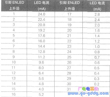
Once the desired current setting is reached, to set the internal registers, the IC pin EN-LED should remain high for at least 3.2ms. To turn off the LED, the pin ENLED is held low for at least 3.2ms. The figure below shows the serial pulse dimming timing diagram.
If dimming control is not required, the IC pin ENLED can be used as a simple on/off logic control. The LED will be enabled or disabled when the pin ENLED is held high and held low for at least 3.2ms. When the LED is turned on, the high brightness is 100%.
2. The mono Class AB audio amplifier MAX8678 integrates a 1.1W direct drive mono Class AB speaker amplifier with low power shutdown and click and click suppression. To set the DC level for the audio output, a common-mode bias voltage of VIN2 is generated inside the IC. Capacitor C4 (see Figure 2) is used to improve PSRR and THD+No audio amplifiers at RL = 8 Ω and VIN = 5 V, with BTL output power (rms) of 1.1 W and THD + N as low as 0.004% (@l kHz). PSRR ≥ 90dB (@lHz).
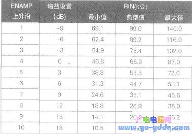
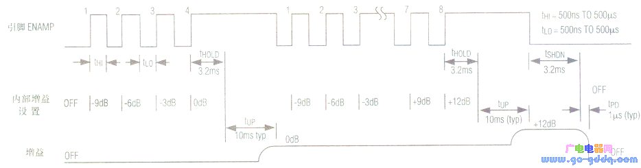
After a low level voltage on the IC pin ENMAP is held for 3.2ms, the audio amplifier will be turned off. The gain of the MAX8678's audio amplifier can be controlled and adjusted via the serial pulse interface. The input amplifier gain setting is adjustable from -9dB to +18dB per stage of 3dB. When the pin ENAMP is high, the amplifier is turned on and the internal registers are set to -9dB. A low-level pulse (width from 500ns to 500μs) is applied to the ENAMP pin to adjust the gain of the amplifier. The gain and input impedance RIN set for each rising edge on pin ENAMP are shown in the table below.
The serial pulse gain adjustment timing diagram is shown below.
The audio amplifier output is a bridged load (BTL) configuration. The amplifier audio input can be either differential or single-ended. The input capacitor CIN and the input resistor RIN (given in the table below) set the -3dB point of the high-pass filter (ie, f-3dB=l/2 πRINCIN).

Not only does the MAX8678 provide shutdown for LED drivers and audio amplifiers, but it also protects against open and short LEDs. When the junction temperature of the chip reaches 160 °C, the IC will automatically turn off. Once the chip temperature drops to 140 ° C, the IC will turn back on.
Mbb Tabbing Ribbon Machine,Mbb Round Ribbon Machine,Solar Tinned Copper Ribbon Machine,New Energy Pv Ribbon Machine
Jiangsu Lanhui Intelligent Equipment Technology Co., Ltd , https://www.lanhuisolar.com