The introduction of two-color LEDs provides a wide design space for the majority of electronic enthusiasts, and its application is very extensive. Porting it to the hi-fi system as a visual display of the speaker protection circuit, it has the same effect.
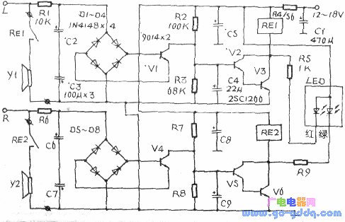
The drawing is a schematic diagram of its working principle. The horn protection circuit is designed to operate independently for the left and right channels. In the figure (taking the left channel as an example), R2, C4 and V2, V3 form a power-on delay squelch circuit to prevent the high current from impacting the speaker. After the power is turned on, the power supply is charged to C4 via R4 and R2. Since the voltage at both ends cannot be abruptly changed when C4 is charged, V2 and V3 are turned off. As the charging time increases, the voltage across C4 gradually increases, about 1.4V. V2 and V3 are turned on, RE1 is pulled in, and speaker Y1 is turned on. The midpoint potential detection circuit of the power amplifier output tube is composed of D1~D4 and the like. When detecting its potential ≥±2V, V1 is turned on, and the charging voltage on C4 is discharged to the ground through e, c and D3 of Vl, V2 and V3 are turned off, and RE1 is released, thereby cutting off the speaker circuit. The right channel works and the component parameters are the same as the left channel.
At the moment when the amplifier is powered on, due to the delay of C4 and C9, V2, V3, v5, and V6 are turned off, and the LED (two-color LED) is not lit. When the delay time is over, the voltage across C4 and C9 is sufficient to turn on V2, V3, V5, and V6, and the LED (red ten green) lights up at the same time and emits orange light (assuming the left and right channel parameters are strictly consistent). If during operation, the midpoint potential of the left channel amplifier rises or falls (≥±2V), V2 and V3 are turned off, and the red LED in the LED is extinguished due to power loss. At this time, the LED should emit green light. Similarly, if the R channel fails, V5 and V6 are cut off, and the green LED in the LEO is extinguished due to power loss. At this time, the LED should emit red light. If both channels fail at the same time 'LED should not illuminate.
If you need to change the delay time, you can increase or decrease the parameters of R2, R7 or C4, C9. C4, C9 is best to use a low-leakage tantalum capacitor, LED can choose φ3mm high-brightness two-color LED. Since the operating current of the LED is large or small, the parameters of R5 and R9 can be slightly adjusted. At the same time, the LED and the current limiting resistors R5 and R9 are connected in parallel across the relays RE1 and RE2 to suppress the anti-peak voltage and prevent breakdown of V2, V3 and v5, V6.
When installing, use three thin wires to pull the LEDs out of the circuit board, fix them on the volume potentiometer knob of the power amplifier panel, and seal them with hot melt glue. The leads need to have enough length.
The horn protector made of two-color LEDs not only displays intuitiveness, but also provides reliable evidence for troubleshooting. It is wonderful, and those who are interested may wish to give it a try.
Sound Bar,Rgb Light Sound Bar,Gaming Sound Bar,Hifi Soundbar Speaker,Echo Wall
Comcn Electronics Limited , https://www.comencnspeaker.com