The MCP6S21, MCP6S22, MCP6S26, and MCP6S28 monolithic ICs from MICROChip are single-ended, rail-to-rail input and output gain programmable amplifiers. Applications include analog-to-digital converter drivers, data acquisition, multiplexed analog applications, industrial instruments, test equipment, and medical instruments. Package, Internal Structure and Pin Function The MCP6S21/2 is available in 8-lead PDIP, SOIC, and MSOP packages. The MCP6S26 is available in 14-pin PDIP, SOIC, and TSSOP packages. The MCP6S28 is available in 16-pin PDIP and SOIC packages with pinouts as shown in Figure 1. Shown.
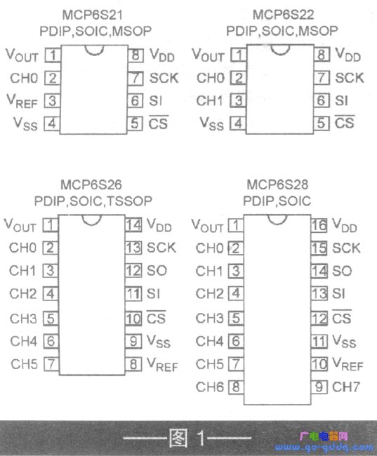
The MCP6S21/2/6/8 chip integrates multiplexer, serial peripheral interface (SPI) logic, operational amplifier, ladder resistor and gain conversion circuit. The internal block diagram is shown in Figure 2.
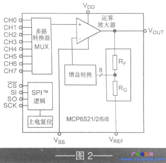
The pin functions of the MCP6S21/2/6/8 are shown in Table 1.
| Pin name | Features |
| VOUT | Analog output |
| CHO~CHT | Analog output |
| VSS | Negative supply voltage terminal |
| VDD | Positive supply voltage terminal |
| SCK | SP1 clock input |
| SI | SP1 serial data input |
| SO | SP1 serial data output |
| CS | SP1 chip selection |
| VREF | External reference |
main feature
The main features of the MCP6S21/2/6/8 are as follows: (1) The input multiplexer can select 1, 2, 6 or 8 channels through the SPI port: (2) There are 8 gains to choose from, ie 1, 2, 4, 5, 8, 10, 16 and 32VN, gain error ≤ l%; (3) rail-to-rail I/O, offset voltage ≤ ± 275μV, typical noise value is lOnV / root Hz (@lOkHz ), the bandwidth is 2 ~ 12MHz; (4) 2.5 ~ 5.5V single power supply, the power supply current is ImA (typical); (5) When the SPI interface sends a shutdown command, the internal operational amplifier is turned off, the output is in a high-impedance state. The digital function MCP6S21/2/6/8 receives commands from the controller using a standard SPI-compatible serial interface, chip select (CS) to initiate communication to low level, serial interface (SI) word "two bytes long" The first byte of the instruction byte is the instruction byte. After one word (16 bits), CS transitions to a high level. PGA devices have two working models, the SPI models O, O and 1, l. In 0, O mode, the clock is idle at low level: in the 1,1 mode, the clock is idle in the high state. In both modes, the Sl data is loaded into the PGA on the rising edge of the clock. Serial output (SO) data is clocked on the falling edge of the clock.
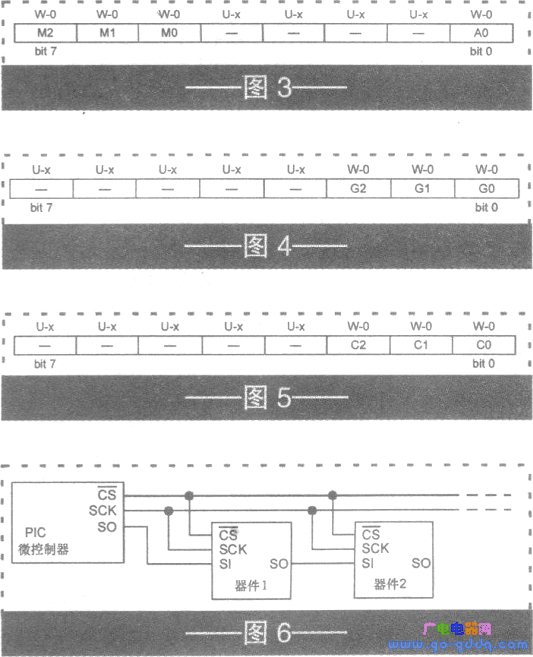
1. The instruction register of the instruction register PGA has three command bits and one indirect address bit (see Figure 3), where: bits 7 to 5 (M2 to MO) are command bits, OOO=NOP (not working); 001= As long as a 16-bit word is transmitted and the CS is raised, the PGA enters the shutdown mode; 010 = write into the register; Oll = NOP; lXX = NOP.
Bits 4 to 1 are not executed and are read as "0" (for future backup). Bit 0 (AO) is the indirect address bit, 1 = the addressing channel register; 0 = the addressing gain register. Legend: R = readable bit; W = writable bit; U = no execution bit, read as "0"; -n = power-on reset (POR) value: "1" = bit is set; "O" = bit Cleared; X= bit is unknown.
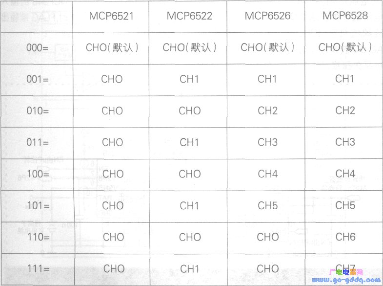
2. The gain setting amplifier can be programmed to produce a binary or decimal gain between 1vN and 32VN. Figure 4 shows the gain register of the PGA. Among them, bits 7 to 3 are not executed, read as "O" (reserved for future use); bits 2 to 0 (G2 to GO) are gain selection bits, 000 = gain is 1; 001 = gain is 2; Gain is 4; 011 = gain is 5; 100 = gain is 8; 101 = gain is 10; 110 = gain is 16; 111 = gain is 32; 3. Change channel if the instruction register is programmed to address the channel register, MCP6S22, The multiplexer inputs of the MCP6S26 and MCP6S28 can be changed. Each channel register is shown in Figure 5. Among them: Bits 7~3 are not executed, read as "O": Bits 2~0 (C2~CO) are channel selection bits (see Table 2).
4, daisy chain configuration Multiple PGA devices can be connected into a daisy chain structure, as shown in Figure 6.
Application circuit
The PGA can have different external reference voltages, as shown in Figure 7. In the figure, the MCP6S21 pin has a VREF of 2.5V and VDD=5V, which allows the PGA to amplify the signal centered at 2.5V. The voltage reference MCP1525 is buffered by the MCP6021, giving a low output impedance from DC to high frequency.
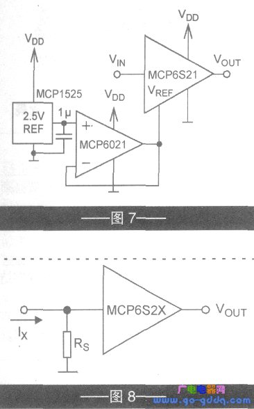
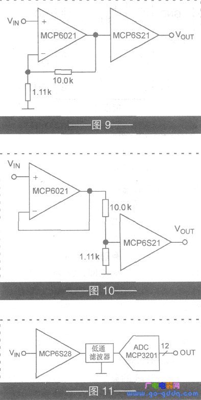
Figure 8 shows the wide dynamic range current measurement circuit of the MCP6S2X. This circuit is used in handheld multimeters. It is easy to set the gain for small signals and easy to set low gain for large signals, so the dynamic range required on the PGA output is lower than its input (up to 30dB). Figure 9 shows the change of PGA gain range. Circuit. In the figure, the gain of the MCP6021 at the front end of the MCP6S21 is 10, so that the gain range of 1 to 32 V/V is expanded to 10 to 320 V. The circuit shown in Fig. 10 can change the gain range from 1 to 32 VN to 0.1 to 3.2 V/V.
Figure 11 shows the circuit using the MCP6S28 as the ADC (MCP3201) driver. The low-pass filter in the figure is used to reduce the noise on the output of the MCP6S28 and acts as an anti-aliasing filter. The filter can be designed using Microchip's FiLTEr-labr software.
This website tries to open micro- and small-enterprise business advertising business; maintenance point recommended items. The fee is affordable and effective! Welcome to contact in QQ or email!
Why do you want to do online advertising contact?
- 0
- like
| Try to find the information you want to see. Inverter Sensor patch three no weight loss camera LCD monitor does not boot digital camera XC9237 projector Switching Power Supply laptop processor IPSUSB skills entrepreneurial black screen water heater can not boot circuit design silent transformer XC6102 without sound XC6112 display regulator no image microwave player successful silent GPS tea no picture XC6222 health XC6372 relay filter ML6209 switch washing machine digital camera description remote control without grating 555 protection circuit cancer self-closing Linux charger mobile phone shutdown noise inverter oscilloscope robot Windows antenna indicator light is not bright fiber life transformer stomach market alarm Hard disk watch embedded system woman maintenance process memory XC9236 converter router interview server kidney RFIDLED driver Konka CDMA instrument Panasonic CCD flashing engine multimeter Apple liver motor resistance keyboard integrated circuit current transformer triode governor power supply LED |
Wireless Bridge,Wireless bridge Access Point,Indoor wireless Bridge,Wireless Bridge Outdoor
Chinasky Electronics Co., Ltd. , https://www.chinacctvproducts.com