Straightening capacitors are usually connected in series on each data line of a differential link, and it has many uses. For example, it can convert the average DC bias level of a signal to suit logic devices of different voltage standards. It protects the transmitter and receiver from the damaging overload events caused by poor power-up sequences. It can be used as part of the circuit function to detect line disconnection. In all of these applications, the DC block circuit must not damage the data passing through it.
Figure 1 shows a typical electrical model of a DC-blocking capacitor that can be cascaded with a serial link. The model shows the input and output of a PCB trace. In fact, the capacitor is soldered to the pads that connect the input and output traces. Electrically, the figure replaces the actual capacitance with a logic diagram that consists of three main components, all of which are standard electrical models of the capacitor. CBULK represents the nominal capacitance of the component. LSERIES is the layout inductance associated with any part of the capacitor body through which the pad, via, and signal current pass. RSERIES is the equivalent series resistance of a component. Figure 1 shows a typical value for a typical EIA 0402 size 6.3V capacitor. The fourth component CBODY is also included in the figure. This component represents the parasitic capacitance between the actual capacitor body and all other adjacent objects, including the reference plane.
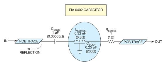
Figure 1. In a DC blocking capacitor, the impedance of CBULK and RSERIES is negligible at 3.125 GHz. The values ​​of LSERIES and CBODY are the most critical.
In any circuit analysis, the first step is to make a quick evaluation of the circuit impedance to see if any components can be ignored. Assuming a link rate of 6.25 Gbps, the frequency of the interlaced 101010 mode (the fastest mode that can be made) is equal to 3.125 GHz. Figure 1 shows the impedance of the four model components at this frequency.
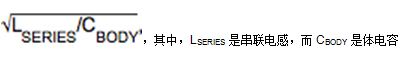
The impedance of the bulk capacitor and the series resistor is negligible; the series inductor and the parasitic shunt capacitor are the main components. The circuit looks like a monostable portion of the trapezoidal model for distributed transmission lines. The impedance of the circuit is equal to
When a rising edge reaches the input end point, if the bulk capacitance of the circuit is too large and the series inductance is too small, the impedance is less than the impedance of the PCB trace, and the circuit is represented as a simple negative pulse. On the other hand, if the series inductance of the circuit is too large and the bulk capacitance is too small, the impedance is greater than the impedance of the PCB trace, and the circuit is represented as a simple positive pulse. By adjusting the inductance and capacitance to the correct ratio, the circuit becomes almost completely electrically transparent. This is the secret of excellent DC blocking performance.
One way to reduce the bulk capacitance is to cut a small circular hole on the reference plane below the capacitor, thereby releasing the capacitance to ground and slightly increasing the series inductance. Both of these results increase the impedance of the circuit.
A simulation engineer may suggest that the value of the bulk capacitance can be actively reduced until the series resonant frequency formed by the bulk and series inductances is compatible with 3.125 GHz. Unfortunately, only in the case of narrowband, adjusting the bulk capacitance in this way will benefit, and still leave parasitic capacitance, producing reflections. Increase the storage capacitor until its impedance is negligible, so just consider the series inductance and bulk capacitance. These components can be balanced to achieve almost ideal performance.
Hardware,gaming hardware,cabinet hardware,hardware fittings
Guangzhou Ruihong Electronic Technology CO.,Ltd , https://www.callegame.com