Application and system structure of entry-level data collector
Entry-level data loggers typically support single-phase power lines for collecting data from automatic meter reading systems (AMR) or new smart meter data with digital outputs. The collected data is typically stored in the flash memory of the collector system (either built-in or external to the microcontroller itself), and the centralized data is transmitted to the upstream network at a predetermined time via the selected communication interface.
An entry-level data collector typically performs a certain amount of preliminary data processing before passing it to the upstream network. For example, combined with a small amount of data sampling and time recording, the data collector can report power usage over a specific period of time, from just a few minutes to a week or a month. Data can also be classified and stored according to different time intervals and screening methods. This helps utilities to analyze power usage trends in detail, granularity of data granularity to individual users, and dynamic adjustments to achieve more reasonable power distribution. After configuration, the data collector can monitor the downstream operation of the electronic meter. If the meter parameters change, or the reporting interval exceeds the tolerance, or a fault or abnormal data is detected, the data collector implements software intelligence, alerts in time, and provides the maintenance team with the information needed for remote repair.
The transmission methods of smart grids may vary from place to place. Therefore, in accordance with local regulations, it is necessary to expand the basic function set. Depending on where the data collector is deployed, data can be transmitted using RS-485, General Packet Radio Service (GPRS) or Power Line Communication (PLC), or externally controlled by infrared or RS-485. Many developers don't design custom designs for each region or market, but instead adopt a "one size fits all" approach to building all the transport methods that the system supports (but not all transports are used simultaneously). This approach may bring economies of scale in manufacturing, but at the same time it will place more demands on the microcontroller.
Entry level data collector system block diagram and resource requirements
Figure 1 shows how to configure the microcontroller for the entry level data collector, and Table 1 lists the general functional requirements for the design. Assume that the device collects data from multiple UART ports and supports a variety of basic functions, including input acquisition, data storage, communication, and maintenance. The design includes a real-time clock RTC for time-stamped data, an optional analog-to-digital converter ADC for real-time power quality checks, and an optional SPI interface for use with external memory or external device communications such as wireless transmission RF modules.
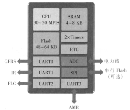
Figure 1 Example of a microcontroller configuration for an entry-level data collector
The power consumption requirements of the microcontroller itself are not listed in Table 1, but in general, the data collector requires efficient power usage. Utilities do not want to increase the extra cost of grid power consumption, and consumers are reluctant to increase electricity bills due to the use of new metering functions. 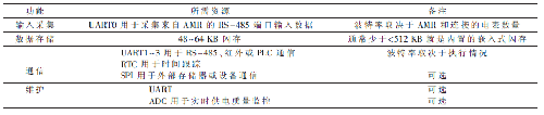
Entry-level data collector component elections and considerations
The NXP LPC1200 Industrial Control Series provides a good solution for entry-level data loggers. As shown in Figure 2, the family uses the ARM Cortex-M0 processor to provide up to 128 KB of flash memory and includes other resources that the data logger can use, such as RTC, ADC, and SPI. 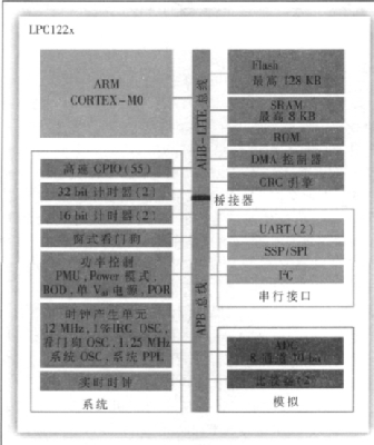
Figure 2 LPC1200 functional block diagram
The LPC1200 Series comes standard with two UARTs, and its unique Special Application Standard Product (ASSP) feature allows the system to additionally support two hardware UARTs. ASSP capabilities allow designers to avoid adding high-end device expenditures while being flexible enough to perform multiple tasks in different applications. For example, its built-in ASSP can also be configured for I2C-to-DMA transfers, pin pattern matching, or analog data logging. Using ASSP reduces the CPU load and reduces the disruption to system operation when handling simple information, minimizing system overhead while customizing microcontroller functionality.
Stator Core welding is a important process for stator core assembly. We are able to use TIG, MIG, LASER weld to meet different requirement for customers. The stator core is an important part of the stator and the main component of the magnetic circuit of the motor. Different sizes of stator cores have different technological processes and application fields. For example, small-sized stator cores are usually assembled by interlocking, and the outer diameter is usually less than 200mm. Large-sized stators are assembled in different ways depending on the motor design, such as stator core by cleating and staor core by welding.
Stator Core By Welding,Stator Iron Core,Bldc Stator Core,Laminated Stator Core
Henan Yongrong Power Technology Co., Ltd , https://www.hnyongrongglobal.com