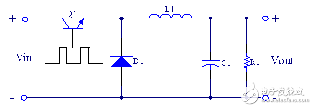
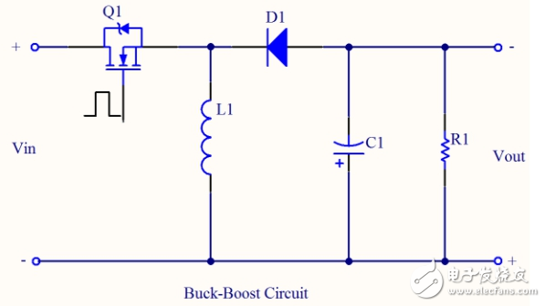
The Buck circuit, also known as the buck circuit, is characterized by a DC-DC conversion circuit with an output voltage lower than the input voltage. The input current is pulsating and the output current is continuous.
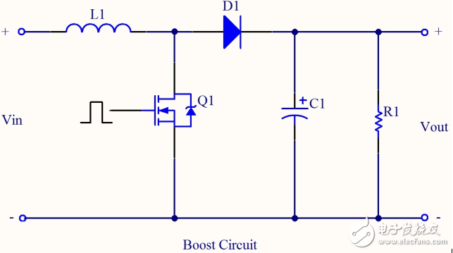
Second, Buck circuit worksWhen the switch Q1 is driven to a high level, the switch tube is turned on, the storage inductor L1 is magnetized, the current flowing through the inductor linearly increases, and the capacitor C1 is charged to supply energy to the load R1. The equivalent circuit is shown in Figure 2.
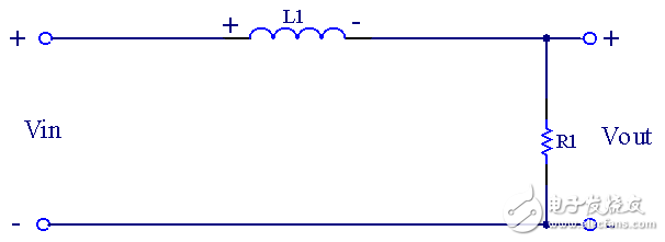
Figure II
When the switch Q1 is driven low, the switch is turned off, the energy storage inductor L1 is discharged through the freewheeling diode, the inductor current is linearly reduced, the output voltage is maintained by the output filter capacitor C1 and the reduced inductor current is maintained, and the equivalent circuit is Figure III
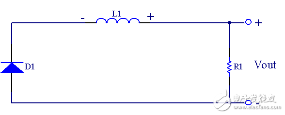
Figure III
Third, the three working modes of the Buck circuit: CCM, BCM, DCM1. CCM Mode : The key point of the original waveform is shown in Figure 4.
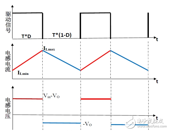
Figure 4
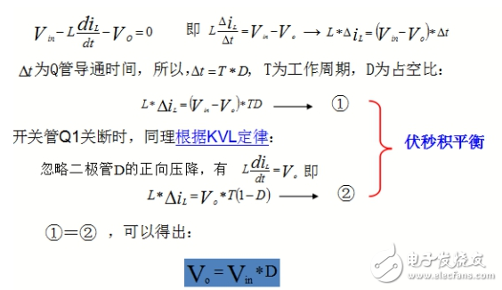
When the switch Q1 is turned on, according to the KVL law:
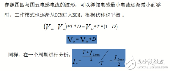
2, BCM Mode : the key point of the original waveform is shown in Figure 5.
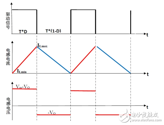
Figure 5
3. DCM Mode : The key point of the original waveform is shown in Figure 6.
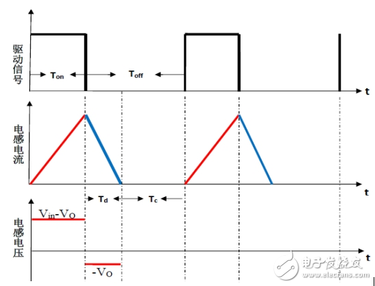
Figure 6
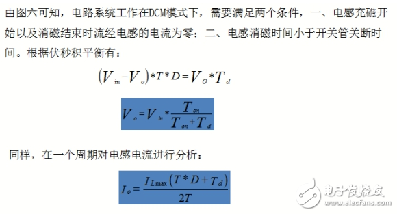
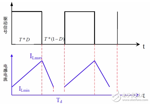
Figure 7
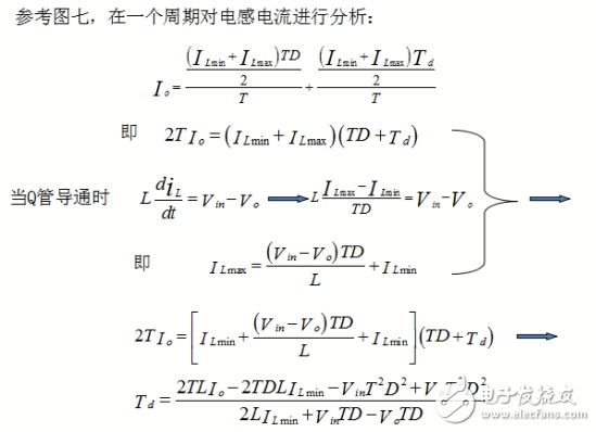
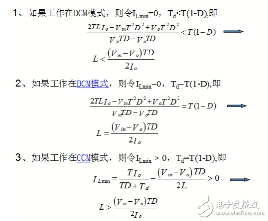
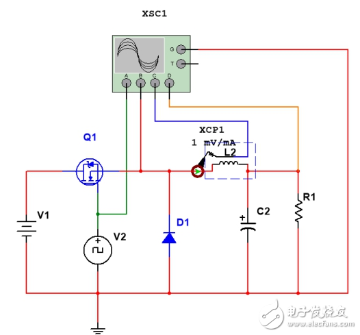
Figure VIII
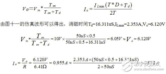
2. CCM mode simulation verification: Based on the above BCM analysis, the inductance of the energy storage inductor is 80uH as the critical point. By the condition that the system works in CCM, the inductance of the energy storage inductor can be set to 120uH. Theoretical calculation:

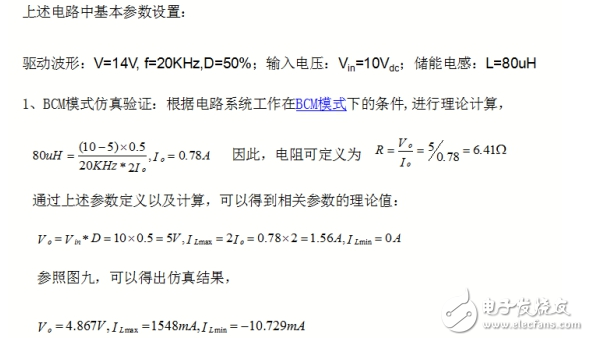
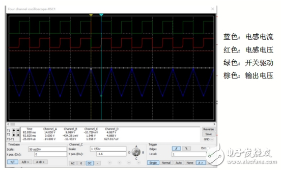
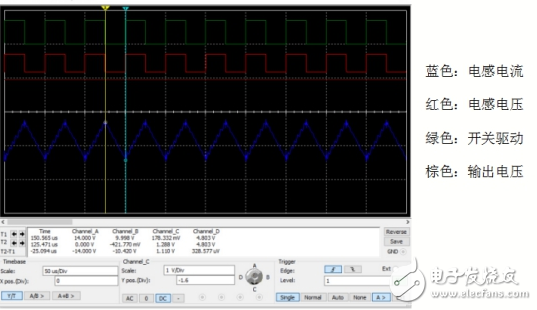
Referring to Figure 10, the simulation results can be obtained.

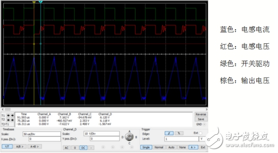
3. Simulation verification of DCM mode: Based on the above BCM analysis, the inductance of the energy storage inductor is 80uH as the critical point. By the condition that the system works in DCM, the inductance of the energy storage inductor can be set to 40uH. Verification key input and output voltage relationship and the relationship between the output average current.
Wall switch and socket ,Champagne wall switch and socket, 16A push switch and socket
Guangdong Shunde Langzhi Trading CO., Ltd , https://www.langzhielectrical.com