A **differential amplifier** is an electronic circuit designed to amplify the difference between two input voltages while rejecting any common-mode signals. It is often referred to as a "difference amplifier" and plays a critical role in many analog systems. This type of amplifier is widely used in power amplifiers, emitter-coupled logic (ECL) circuits, and as the input stage of operational amplifiers.
When the transistors Q1 and Q2 are matched in characteristics, their output voltages Va and Vb change proportionally. For example, if Va increases by +1V, Vb also increases by +1V, resulting in Vout = Va - Vb = 0V. This cancellation of common-mode changes makes the differential amplifier ideal for amplifying DC signals and reducing noise.
The output voltage of a differential amplifier can be expressed as:
$$
V_{out} = A_d \cdot V_d + A_c \cdot V_c
$$
Where $ A_d $ is the differential gain, and $ A_c $ is the common-mode gain. To improve the signal-to-noise ratio, it's essential to maximize $ A_d $ while minimizing $ A_c $. The ratio of these two gains is known as the **Common-Mode Rejection Ratio (CMRR)**:
$$
CMRR = \frac{A_d}{A_c}
$$
The common-mode gain $ A_c $ is typically calculated using the formula:
$$
A_c = \frac{2R_L}{2R_E}
$$
As $ A_c $ approaches zero, CMRR becomes very large, indicating excellent rejection of common-mode signals. Increasing $ R_E $ helps reduce $ A_c $, thereby improving the CMRR. In a perfectly symmetrical differential amplifier, $ A_c = 0 $, so the output voltage depends only on the differential signal:
$$
V_{out} = A_d \cdot (V_1 - V_2)
$$
This means that if both inputs receive the same signal, the output remains unchanged, effectively eliminating noise or interference that affects both inputs equally.
To suppress common-mode signals further, engineers often increase $ R_E $ or replace it with a constant current source, which provides high internal resistance and enhances performance.
A differential amplifier can be thought of as a more advanced version of a single-ended amplifier. By grounding one input, you can convert it into a single-ended configuration. Many control systems use this setup, applying feedback to one input and a reference signal to the other, commonly found in motor control, power supplies, and precision measurement devices.
In discrete electronics, differential amplifiers are implemented through balanced circuits, which are fundamental to most operational amplifier designs.
### Single-Ended Output Differential Amplifier Circuit (Unbalanced Output)
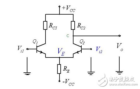
When the output is taken from the collector of either transistor Q1 or Q2, it’s called a **single-ended output** or **unbalanced output**. In such configurations, the amplitude of the differential output is doubled, but the ability to suppress common-mode signals is reduced.
If both inputs rise together, the collector voltages of Q1 and Q2 decrease equally, but since only one is measured, the output does not return to zero—this can lead to **zero drift**. However, increasing $ R_E $ introduces negative feedback, which helps suppress common-mode signals and stabilize the output.
When a differential signal is applied (e.g., $ V_1 = -V_2 $), the currents through Q1 and Q2 change oppositely, but the total current remains constant. This ensures that the emitter voltage stays stable, allowing the differential signal to be amplified effectively without unwanted distortion.
High Frequency Flyback Transformer
RM10 electrical transformer,EE13 high frequency transformer,EE10 LED transformer,EE16 flyback transformer
IHUA INDUSTRIES CO.,LTD. , https://www.ihuagroup.com