Analysis of Differential Amplifier Circuit in Analog Electronic Circuit

**Principle of Differential Amplifier** A differential amplifier, also known as a difference amplifier, is an electronic circuit that amplifies the voltage difference between two input signals with a fixed gain. It is often referred to simply as "difference" because it emphasizes the variation between the two inputs rather than their absolute values. These amplifiers are widely used in various applications such as the input stage of power amplifiers and emitter-coupled logic circuits (ECL). 
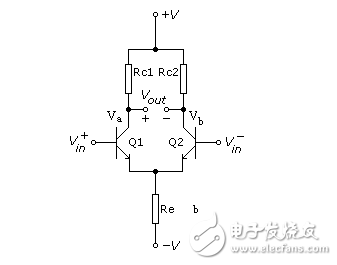
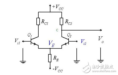
Below is a diagram illustrating the basic operation of a differential amplifier circuit:

Analysis of Differential Amplifier Circuit in Analog Electronic Circuit

When the transistors Q1 and Q2 have similar characteristics, changes in Va and Vb will occur simultaneously. For example, if Va increases by +1V, Vb will also increase by +1V. As a result, the output voltage VOUT = Va - Vb remains at 0V, meaning the changes cancel each other out. This property makes the differential amplifier effective for amplifying DC signals. If the two input signals are identical, the output voltage Vout can be expressed as:

Analysis of Differential Amplifier Circuit in Analog Electronic Circuit

Here, Ad represents the differential mode gain, while Ac represents the common-mode gain. To improve the signal-to-noise ratio, it’s important to increase Ad and reduce Ac. The ratio of these two gains is called the Common-Mode Rejection Ratio (CMRR), which measures how well the amplifier suppresses unwanted common-mode signals. The common-mode gain Ac can be calculated using the formula: Ac = 2Rl / 2Re The CMRR is defined as the ratio of differential gain to common-mode gain:

Analysis of Differential Amplifier Circuit in Analog Electronic Circuit

As shown, when Ac approaches zero, CMRR becomes very large, indicating strong rejection of common-mode signals. Increasing the value of Re reduces Ac, thus improving CMRR. In a perfectly symmetrical differential amplifier, Ac is zero, and the output voltage becomes:

Analysis of Differential Amplifier Circuit in Analog Electronic Circuit

The common-mode gain refers to the amplification of the same signal applied to both inputs. If this gain is zero, the output remains unaffected by noise or common-mode disturbances. To minimize the common-mode gain, the resistance RE is increased, and often a constant current source with high internal resistance is used instead of a simple resistor. This helps stabilize the circuit and improves its performance. A differential amplifier is essentially a more advanced version of a single-ended amplifier. By grounding one of the inputs, a single-ended configuration can be achieved. Many systems use differential amplifiers with feedback on both inputs to achieve negative feedback, which is commonly applied in motor control, regulated power supplies, and measurement instruments. In discrete electronics, differential amplifiers are often implemented through balanced circuits, and they form the core of most operational amplifier designs. **Single-Ended Output Differential Amplifier Circuit (Unbalanced Output)**

Analysis of Differential Amplifier Circuit in Analog Electronic Circuit

When the output is taken from the collector of either Q1 or Q2, it is referred to as a single-ended or unbalanced output. In this configuration, the amplitude of the differential output is doubled. However, the common-mode signal cannot be effectively suppressed. When both inputs increase simultaneously, the collector voltages VC1 and VC2 decrease, but since the output is only taken from one side, the output does not go to zero, resulting in zero drift. Increasing the value of RE can help reduce the common-mode gain by introducing negative feedback. When both inputs increase equally, the total emitter current IE rises, causing the emitter voltage VE to increase. This creates a negative feedback effect, reducing the gain of Q1 and Q2, and thereby suppressing the output. When a differential signal is applied, where Vi1 = -Vi2, IC1 increases and IC2 decreases. Since the total current IE remains constant, the emitter voltage VE does not change. In this case, increasing RE enhances the differential gain, while still maintaining some level of negative feedback to stabilize the circuit.

LAN Transformer

Lan Transformers For Automotive Battery,Ferrite Core Lan Transformer,Ethernet Isolation Transformer,Pulse Ethernet Transformer

IHUA INDUSTRIES CO.,LTD. , https://www.ihuagroup.com