Abstract: Traditional medical electronic devices do not have wireless capabilities and cannot perform medical monitoring anywhere, anytime. In this paper, an IPV6-based routing protocol for medical electronic wireless networks is proposed. Based on the domestic CK610 CPU and TI's CC2520 RF chip, basic wireless communication is realized, and the medical inspection results are displayed on the PC through a graphical interface.
0 Preface
In the field of medical electronics, in terms of embedded processors, the most widely used and mainstream ARM.MIPS are CPUs produced by foreign manufacturers, while domestic CPUs with independent intellectual property rights are rarely noticed.
In addition, with the advancement of wireless technology and the reduction of the cost of wireless devices, medical electronic wireless will be the future development trend. At present, some enterprises and groups have made research and development in the direction of medical electronic wireless, but the current network protocols used by wireless medical electronics are basically based on IPV4, and the application of more advanced IPV6 networks to wireless medical electronics is The problems that must be faced in the future development.
This paper mainly designs an IPV6-based network protocol for medical electronics, and writes a routing protocol program and RF adaptation program for implementing the protocol, realizing the wireless function of medical electronics.
1 System Overview
The main system architecture is shown in Figure 1: The single node consists of the CK610 development board and the medical electronic board and the CC2520 RF chip. The controller is connected to the PC for the common node. Linux is used as the operating system of the CK610, and the CK610 is simulated by operating the FPGA IP core. The SPI is used to control the CC2520, and the CC2591 is controlled by the pin of the CC2520.
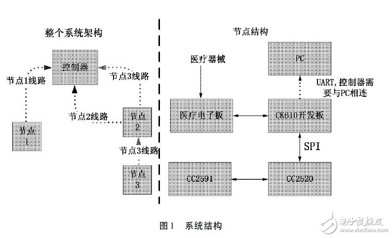
In a network system of medical electronic applications, there can be multiple nodes, but only one controller. The end point of all node data transmission is the controller, and the farther nodes can be forwarded by other nodes to transmit data.
2 network protocol design
In order to implement the system architecture of Figure 1, an IPV6-based network protocol needs to be designed for the system.
2. 1 routing algorithm design
To establish and maintain a wireless network, three forms of data packets must be sent and processed, each of which is a routing request packet. Route broadcast packets and route report packets.
Each node in the network maintains a routing table, and each item of the routing table is a node adjacent to the node. The contents of a typical node routing table are shown in Table 1.
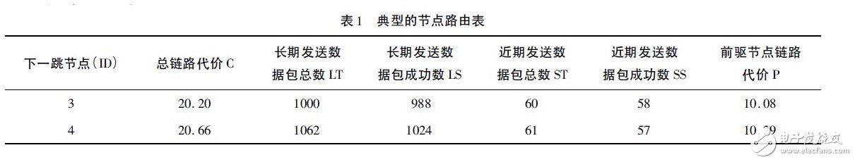
Each node sorts each item in the routing table according to the total link cost, and the corresponding node with the lowest total link cost is selected as the default route. As long as the node has data to send or forward, the data will be sent to the default. routing.
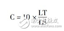
The total link cost represents the quality of the link channel. The smaller the value, the better, which is the sum of the local link cost and the predecessor link cost. The precursor node link cost is obtained from the route broadcast packet periodically sent by the node. If the predecessor node is a controller, the predecessor node link cost is 0. The local link cost refers to the link cost of the channel between the own node and the predecessor node, indicating the communication channel quality, and the smaller the value, the better. In order to calculate the local link cost, it is necessary to maintain the total number of long-term transmission packets LT. The number of long-term transmission packets success LS. The total number of recently transmitted packets ST and the number of recently transmitted packets success SS.
ST and SS count from zero. Each time the node sends data (including retransmission), the total number of sent packets will be increased by 1 in the near future, and the number of successful packets sent in the near future SS is incremented by 1 for each successful data transmission. The two values ​​are cleared after the RTIMER timer expires and the total number of long-term transmitted packets LT and long-term transmitted packet successes LS are updated. The total number of long-term transmission packets LT and the number of long-term transmission packets are updated when the RTIMER timer expires. The updated rule is to add the current total number of long-sent packets LT plus the total number of recently transmitted packets ST as new long-term transmission data. The total number of packets LT will be the long-term transmission packet success number LS plus the recent transmission packet success number SS as the new long-term transmission packet success number LS. If the total number of long-term transmission packets LT is greater than 0XF000, the packet will be sent for a long time. The total number LT and the long-term transmission packet success number LS are shifted to the right by one. There are two advantages to doing this:
(1) Avoid the long-term transmission of the total number of packets LT and the number of long-term packets sent successfully. The LS is infinitely increased to be unstorable.
(2) The farther away from the current time, the smaller the influence of the statistical value on the calculation of the link cost, in line with the natural law.
The calculation formula for the local link cost is as follows:
The node updates the routing table link cost information when it receives the route broadcast packet of the neighbor node and the RTIMER timer expires.
2. 2 Joining the network node
When node 1 wants to join the network, it must first send a route request packet to apply to join the wireless network. After receiving the request, the controller sends a route broadcast packet to node 1. After receiving the route broadcast packet, node 1 adds the network address prefix to its own node ID to form its own network address, and adds the controller to its own routing table. The default route for node 1 is now the controller.
At the same time, node 1 will immediately start TTIMER and RTIMER two timers. When TTIMER expires, node 1 will send a routing report packet to the controller, and the controller will receive the packet to update the network topology in time.
When the controller's RTIMER expires, it also sends a route broadcast to node 1, and node 1 immediately updates the routing table.
During the operation of the network, there are new nodes to join the network, and the node can communicate directly with the controller. The situation at this time is more complicated than when the first node joins the network. When node 2 starts, it first sends a route request packet. After receiving the packet, the controller and node 1 will send routing broadcast packets. After receiving these packets, node 2 will modify its own network address, and both controller and node 1 will be updated. Add to your own routing table. When the RTIMER timer expires, a route report packet is sent to the controller. After a period of stabilization, the contents of the route report packet should include node 1 and the controller.
After the RTIMER timer of node 1 expires, the route broadcast packet is sent, the controller and node 2 can receive it, node 2 updates its routing table, and the RTIMER timer of node 2 expires, and the route broadcast packet is also sent. 1 Add node 2 to your own routing table.
If the newly joined node cannot communicate directly with the controller, that is, node 1 already exists in the network, node 2 cannot communicate with the controller. When node 2 starts, it also sends a route request packet. This packet can only be received by node 1, so node 1 replies to node 2 with a route broadcast packet, which can be received by both node 2 and the controller. After node 2 receives this packet, it will set its own network address and add node 1 to its own routing table. At this time, the routing table of node 2 has only node 1, so the default route of node 2 is node 1. When the TTIMER timer of node 2 expires, it will send a routing report packet to the default route, that is, node 1, and node 1 receives Route the report packet and forward it to the controller. Node 1's RTIMER timer expires, a route broadcast packet is sent, and node 2 updates its routing table.
The route broadcast packet is sent when the RTIMER timer of node 2 expires, and node 1 updates the routing table when it receives the packet.
2. 3 Network maintenance and update
During the operation of the network, the channels are constantly changing. In order for the entire network to work properly, network parameters must be updated in a timely manner.
The maintenance and update of the network is implemented by the RTIMER timer of each node. When the timer expires, the node broadcasts the route broadcast packet, and all the nodes that receive the broadcast packet update their routing table information, so that the whole The channel information of the network has been updated.
We are professional manufacturers and leading suppliers of ball shape led in China. All ball shape led products offered in our factory are with competitive price.
Ball shape LED Video display: Model: JoyLED-Ball; LED Video Ball; UL,CE,Rohs,FCC Approved; 5 Years Warranty; LED Video Ball, 360 Degree Video 3D Led Display with high brightnes s for indoor and outdoor use. JoyLED Ball shape LED Display is widely applicated in restaurant, hotel, meeting room, etc.
Ball shape LED Video display Features:
1.360 degree viewing angle, nice video, pictures visual effect,Display different videos like normal screens
2.Aluminum structural design, can be movable, suspended,Excellent cooling channel design,Special design LED modules ensure seamless assembly.
3.Extra-high brightness and can be adjustable,It can meet the needs for different environmental applications.
4.Support Synchronous,Asynchronous,Wifi,3G,4G control.such as linsn led,novastar led control system.
5.LED Ball Diameter 1.2m, 1.5m, 1.8m, 2m, 2.5m ,3.6m, 4m for you for choice.adopt small unit module assembling technology which can make Circular Led Display, more smooth and perfect.
6.Support hanging,floor stand,embedded installation,etc.
7.Widely used in hotel, stage, club, museum, exhibition hall, shopping mall,etc
Ball shape LED display,LED Video Ball,360 Degree Video 3D LED Display with High Definition For Advertising Purpose

Ball shape LED Display
Circular Led Display,Circular Flexible Led Display,Circular Advertising Led Display,Circular Video Led Display
Shenzhen Joy LED Display Co., Ltd. , https://www.joe-led.com