The FM radio receiver module is a standard feature in the most modern mobile phones. Short-range FM transmission (Tx) has recently become a popular means of transferring audio from a portable MP3 player to a home or car radio, a feature that will soon be available for mobile phones.
Laird Technologies has developed a built-in antenna RadioAnt for mobile phone FM radio reception that provides similar performance to an outdated wired earphone antenna through the integration of a radiating device with a joint design preamplifier.
This approach has several advantages over traditional passive solutions. One of them is to effectively eliminate the requirement for an antenna impedance of 50 ohms. This is a very important frequency of the FM, which can reach a radiation impedance of about 1 meter. The inherent radiant amplifier impedance interface is not around 50 ohms in the active antenna, the output can be adjusted to any impedance level, and the input to the receiver appropriately includes 50 single-ended or 200 differential impedances.
The gain of the preamplifier suppresses approximately 6dB of noise from the FM receiver. This is equivalent to using a passive antenna with a high gain of 6dB. The high gain of the active antenna provides a more suitable signal level for the FM receiver due to the limited dynamic range of the standard receiver automatic gain control. However, higher gain (due to noise and equal amplification of the signal) does not increase the signal-to-noise ratio (SNR) at the RF frequency, which greatly increases the SNR of the downconverted audio frequency. However, the need for impedance loading is eliminated, which severely reduces gain and increases antenna noise, and the amplifier does not require unconditional stability.
This kind of active antenna does have drawbacks, but it can cope. Specifically, the design and features are more complex, and the preamplifier consumes power and PCB area. In addition, active devices must be protected from ESD and do not degrade sensitivity. Most importantly, stability and linearity must be achieved without a resistive load, even if the antenna has an impedance close to an open or short circuit at the input of the amplifier.
Active antenna characteristics
The main indicator that benefits the active antenna is the total gain (antenna + amplifier) ​​normalized by the total output noise temperature G/T (referred to as G to T). At present, if the amplifier gain is increased, the output noise will increase and there is no improvement in G/T. For example, G/T lossless, fully matched short dipole or loop antenna is -22.8 dB/K at room temperature (with 1.8 dBi directionality, 1.8 dBi-10 log (290 K)). The concept of G/T degradation proposed here and the fully matched lossless short dipole antenna is similar to the concept of noise figure (NF) because the SNR is compared at two different nodes, but at a 290 K noise temperature. The input below (such as a metric defined as NF) does not require a matching source. In general, since most electrical small antennas have a directivity of 1.8 dBi, the gain G is considered to be an "average gain" at various angles, which is consistent with standard antenna efficiency (so, the maximum is 0 dB or 100%). In the entire article of this article, gain is synonymous with efficiency and, therefore, does not include directionality. For example, G/T drops by 10 dB and system performance is equivalent to passive antenna -10 dB efficiency (if all antennas are connected to a noiseless receiver).
In addition to the antenna characteristics, the degradation value of G/T in practical applications is affected by two external factors: the ambient noise temperature Ta that increases the output noise, and the antenna output noise Tout (and therefore the G/T). Receiver noise figure NFre. It has been shown that due to the artificial RF noise, the value of Ta is much higher than the room temperature T0 (e.g., 290K or -174 dBm/Hz) at the FM frequency. The increased noise level means that the effects from active device and resistance noise contribution are reduced, unless the built-in antenna is used, the gain of the radiating device is so low that the physical temperature of the antenna determines the noise temperature. In addition, a high background noise level means that the efficiency requirements of the radiating device can be reduced, and the ideal low noise situation is not greatly reduced as much as G/T. This can be qualitatively understood as a more efficient antenna that receives a larger signal level than an inefficient antenna, but it also receives more noise. Therefore, the SNR at the output of the antenna is not significantly improved.
The second effect is NFrec, which also contributes noise to the output of the antenna, but can be made insignificant by choosing a very high gain amplifier (Gamp NFrec), which improves the NF performance of the system compared to passive antennas. It should be noted that the two effects of background noise and NFrec are usually not divisible, for example a high background noise temperature can achieve a receiver-independent noise figure and vice versa.
If the efficiency of the radiator is known to the gain Gamp of the amplifier (assuming the antenna is at room temperature T0 and "understand" the surrounding noise temperature Ta), the active antenna G/T can be calculated by the following equation (where the temperature unit is K) Degraded value:
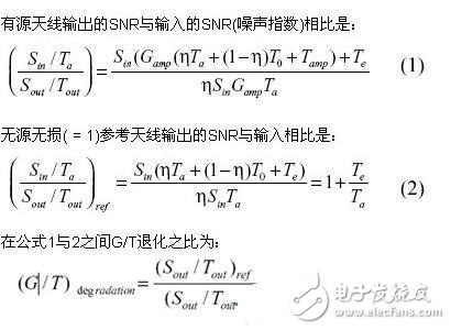
Table Gas Cooker,Gas Stoves,Gas Cookers,Tabletop Stoves
xunda science&technology group co.ltd , https://www.gasstove.be