1 Introduction
Important units or key components such as measuring instruments, data acquisition systems, servo systems, and robots need to be recorded in the state of abnormal power failure and necessary system configuration. The battery used often has a reduced life due to long-term floating charge and needs to be replaced periodically. Super Capacitor combines the advantages of high power density of conventional capacitors and high specific energy of rechargeable batteries. It can perform high-efficiency fast charge and discharge, and can be floated for a long time. It is excellent in high-current charge and discharge, charge and discharge times, and life. The battery is developing into a new, efficient and practical energy storage device, which is a new energy device between the rechargeable battery and the capacitor. In this paper, a high-efficiency, high-current Boost power-down backup power supply is designed using supercapacitors.
2 Super capacitor capacity and topology selection
The power supply achieves short-time power-down protection, and its configuration needs to be optimized, that is, the use of the smallest possible capacitance capacity to obtain the longest use time. With the Buck structure, the efficiency will be improved, but there will be a large capacitance charge that cannot be utilized; the back pressure generated by Buck-Boost using the buck-boost structure will be difficult to directly use; the topology using high-frequency transformer isolation is economical. Sex, efficiency, power density and other aspects have certain limitations; in summary, this paper uses a non-isolated boost topology that can make the capacitor capacity reasonable. The main technical indicators are as follows: super capacitor voltage available range 3V-5V, maximum input current 18A~ 20A, output voltage +5V@5A, hold time 10 seconds. Due to the short power-down protection time, power component derating is not too harsh.
The supercapacitor acts as an energy storage component. Under normal conditions, the design is powered by a 5V supply and simultaneously charges the supercapacitor. When the external power supply is powered down, all power requirements of the system are completed by the super capacitor. In this design, the supercapacitor part is composed of two capacitors with a withstand voltage of 2.7V and a capacitance of 220F. In order to achieve better voltage equalization effect, two 1M resistors are used to perform two super capacitors. Pressure.
3 backup power main power design
3.1 Design of main power topology
The topology of the main power circuit is Boost boost circuit. The circuit is shown in Figure 1. It mainly includes three parts: super capacitor, boost topology and LC filter.
In the Boost power topology, the inductor and MOSFET are subjected to a large current, up to 20A, and the MOSFET's current resistance and necessary heat dissipation must be considered. The value of the inductor should be chosen appropriately (2.2uH is used in this paper). Since the necessary gain is needed when the input voltage is low, the internal resistance of the MOSFET and the inductor will affect the voltage gain, that is, the maximum duty ratio exists. When this value is exceeded, the voltage gain decreases, and the efficiency becomes low. It is easy to cause the inductor to saturate due to excessive inductor current, thereby burning the MOSFET or the inductor. The MOSFET needs to have a small on-resistance and the DC impedance of the inductor needs to be small.
The LC filtering part mainly includes an inductor and a capacitor, and the filter series can be selected through experiments. This design uses 0.9uH inductor as the filter inductor, and the filter capacitor is connected in parallel by 2200uF and 0.1uF.
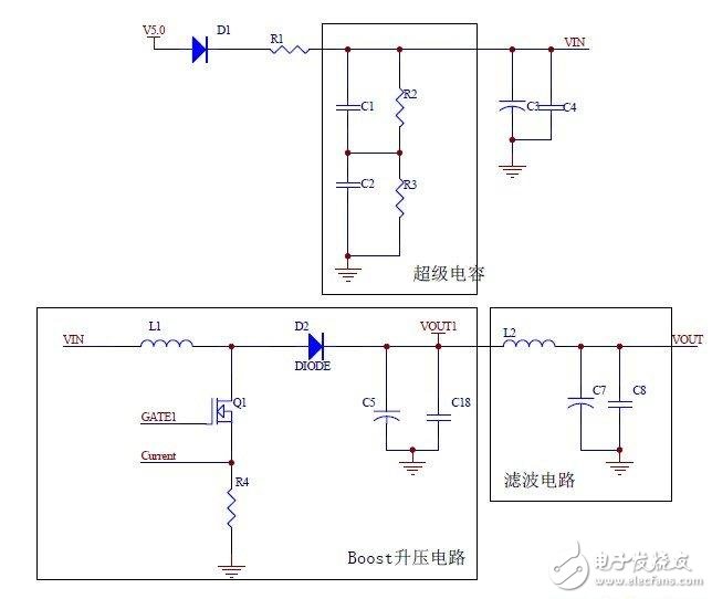
Figure 1 Schematic diagram of the main power circuit
3.2 Drive Control Design
The drive control uses UCC2813, the switching frequency is 100K, as shown in Figure 2, the MOSFET is directly driven by the output Gate1 of the chip.
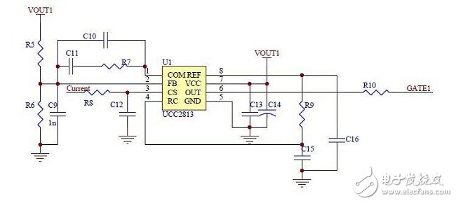
Figure 2 drive control circuit
Offering Room Oil Diffuser, Hotel Scent Diffuser, Hotel Aroma Diffuser From China Manufacturer.
Hotel Scent Diffuser is to spread the scent to the corners of the hotel. The fragrant hotel will let you experience the warm feeling, friends who are out of the house, tired and tired for a day, always want to find a warm harbor to take a break. But suffering from all the hotels is the same, there is no special characteristics and style, just choose the nearest one is the practice of most of us.
How can I attract customers to stay with? Hotel Aroma Diffuser is the most direct and effective way. After the hotel is fragrant, it will give us a special sense of favor. We don`t need to spend time thinking, going to see, checking, just passing through that place, smelling the familiar taste, we already have a sense of belonging, This feeling is the feeling of home. Hotel Diffuser helps the hotel to create a warm harbor for customers, allowing customers to park here, and the scent is the designated light on the parking lot.
Hotel Diffuser
Room Oil Diffuser,Hotel Scent Diffuser,Hotel Aroma Diffuser,Hotel Diffuser
Shenzhen Dituo Electronic Co.,Ltd. , https://www.sz-dituo.com