With the wide application of battery energy, the depletion of petroleum resources and environmental pollution, electric vehicles have attracted more and more attention due to their advantages in energy conservation and environmental protection. In the research and development of electric vehicles, the research and development of vehicle batteries and their management systems Manufacturing occupies an important position. The main problems in the application of electric vehicle power battery are: in the production process, the battery technology, technology and group technology can not guarantee the initial performance has good consistency; during use, overcharge, over discharge, over Temperature, overcurrent, etc. are very sensitive, and the occurrence of such a situation can significantly shorten the battery life and even cause the battery to be scrapped. The battery pack is a series of dozens or even hundreds of single cells, and there is an inconsistency between the cells. With continuous charge and discharge cycles, the inconsistency between the batteries is intensified, and the available capacity of the battery pack is limited by the smallest capacity. Battery restrictions. For these situations, the initial performance of the battery must be optimized by the optimization of the production process of the enterprise, the control of the key parameters of the production process, and the problems in the use process need to be solved by the battery management system. This design is based on STM32F107 as the core controller to control the battery pack information collection and basic control module work and obtain data through the CAN communication network with C8051F500 single chip as the core. It mainly realizes over-voltage discharge equalization of single battery, over-current protection, over-temperature protection, over-discharge protection, and reports and stores the working status of the overall battery pack through the upper controller.
1 hardware design
1.1 System Architecture
The battery pack structure monitored and managed by the system is: firstly connect a certain number of lithium ion batteries in series, connect several battery strings in parallel into one battery group, and finally connect several battery groups in series to form an integral battery pack, the serial-parallel multiplexing organization The form is advantageous for performing charge and discharge start-stop operation of a single string battery, and reducing battery capacity inconsistency generated during use. The composition of the management system is shown in the figure. Each battery string is equipped with a secondary controller for monitoring management, collecting current, voltage, temperature and other data and uploading, controlling battery string start and stop and equalization operation, and the first controller is dual CAN control. The structure of the device, the CAN1 controller and the secondary controller form the CAN network of the battery pack, and the CAN2 controller and the battery pack of the main control board form an internal first-level CAN bus network, which is responsible for reporting the working status of the battery pack to the main control board and subordinate to the second The level controller communicates the command, and the CAN2 controller of the main control board is connected to the vehicle CAN bus. Since each battery pack has a series structure, the increasing voltage relationship affects the secondary controller, so DC/DC conversion is required for power supply.
1.2 main controller, primary controller architecture
The core controller of the main controller and the first controller is completed by STMicroelectronics' STFM32F107. The STM32F107 is a high performance, low cost, low power 32-bit RISC microprocessor with ARMCortex-M3 core and 256 internal. kB's Flash and 64 kB SRAM have sufficient programming space, clocked at 72 MHz, and are sufficient for real-time management of lower-level controllers. It includes: basic power supply circuit, reset circuit, standard JTAG debug port, dual CAN physical layer circuit, EEPROM memory, which is the best solution for this system design.
1.3 secondary controller architecture
Due to the small voltage of the lithium-ion battery cell, it is generally about 4 V, and the overall battery pack voltage is as high as several hundred volts, and the length of the single-string battery is also more than 15, and the commonly used battery measuring chip is expensive and can only be used. Monitoring 6 or 12 cell voltages, considering the decision to design a secondary controller with C8051F500 as the core. Compared with the dedicated battery measuring chip, this design has the disadvantage of low precision, and the advantage is that the measured data can be used first. The calculation process is performed without relying entirely on the instructions of the superior controller.
The C8051FS00 processor is designed according to the AEC-Q100 test standard. It has a wide operating voltage, wide operating temperature range, strong anti-interference ability and built-in CAN and LIN bus controllers. It is suitable for automotive electronics and industrial control applications. The chip has 32 I/O ports, the number of interfaces meets the needs of monitoring battery string operation, with 12 bit ADC, the minimum setup time of each channel "50μs is the total time of a cycle inspection "1 ms, enough to support The real-time monitoring of the battery string, the controller architecture is shown in Figure 2.
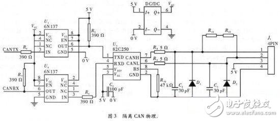
The physical layer circuit of the CAN bus with isolated drive is shown in Figure 3. In addition, there are external devices such as DC/DC power supply and C2 online debugging interface.
2 software design
2.1 Secondary Controller Software Process
(1) Coefficient correction procedure. Because the total number of batteries is extremely large, in order to reduce the production cost and space of the system, the voltage measurement uses a relatively simple resistor divider, and the current measurement uses a resistance sampling method. To compensate for the error caused by the resistor, a correction coefficient is preset. Before each circuit board is put into use, it can connect 5 V standard voltage to all voltage measurement ports, and 10 A standard current is applied across the sampling resistor. The program automatically modifies the coefficients based on the measured values ​​to improve the accuracy of the work.
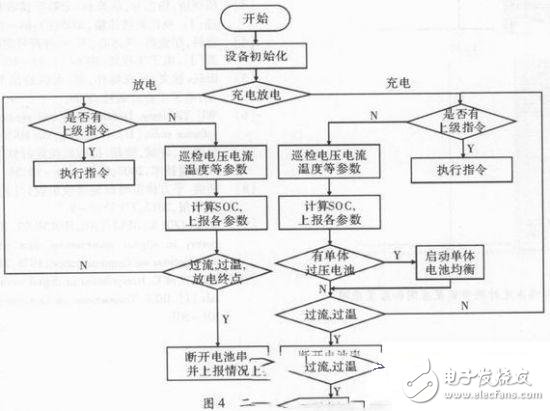
(2) Software process. As shown in Figure 4, when the program starts running, first initialize the system clock and some variables inside the C8051FS00, and then initialize each I/O port, timer, interrupt, ADC working mode and CAN bus working mode, and then according to the measurement. The two I/O data of the current determine whether the battery pack is currently charging or discharging, to select different control schemes, and then to detect whether there is an instruction issued by the first-level controller, and if so, execute the instruction, otherwise the ADC will inspect each I/O. The input voltage is programmed by the pre-stored coefficient to the terminal voltage of each battery, the current and temperature of the battery string. Finally, the SOC of each battery is calculated. Considering the computing power of the C8051F500, an ampere-time integration method with moderate accuracy and computational complexity is adopted, and the temperature, voltage, voltage-time gradient and the like are corrected. At the same time, the total voltage, current, temperature and total SOC are reported in real time to the first-level controller. If the single-cell battery voltage is too high during charging, the corresponding MOS tube is turned on to balance the charging. When over-temperature, over-current or discharge end occurs, disconnect the battery and report all data when disconnected to the primary controller. Otherwise, the main program continues to judge whether there is an instruction to cycle the above process.
2.2 First-level controller software flow
(1) Receive the data uploaded by the secondary controller. There are two main types of data: one is the current, voltage, temperature, and remaining power of each string of batteries that are uploaded at any time; the other is when a string of batteries stops working for any reason. Full data and stop reason.
(2) SOC calculation, the SOC calculated here is based on the current, voltage and temperature uploaded in real time to calculate the remaining battery capacity, because the STM32F107 chip computing power is stronger than C8051F5 00, so the calculation model here uses the fuzzy neural network method.
(3) The instructions are issued to the secondary controller. There are two kinds of instructions here: one is to request the full data of the current working condition, mainly to save the historical data before parking or manually request to view; the second is the SOC during charging and discharging. When the battery string is significantly higher/lower than other battery strings, let the battery string be suspended for a period of time, which is beneficial to smooth the inconsistency between the batteries during use. When there is a large difference between the uploaded SOC and the calculated SOC, the situation is uploaded to facilitate checking and correcting the model coefficients.
(4) Upload data to the main controller. The data here includes the voltage, current and SOC of the battery pack, and the voltage, current, temperature and SOC of the corresponding battery, in addition to the active or the main controller. In addition to the work situation, there are reports of various unexpected situations.
2.3 main controller software flow
The task of the main controller is to report the operation of the battery pack to the vehicle controller, and to communicate instructions to the first-level controller according to the requirements, similar to the first-level controller, but each battery pack may cut off a certain battery string, resulting in The SOC is abrupt, so there is no operation to calculate the SOC of each battery pack.
3 Conclusion
This paper proposes a battery pack monitoring and management system with STM32F107 as the core controller and interconnected with C8051F500 as the core controller through CAN bus. It can efficiently manage the battery, provide the driver with residual power information and extend the battery usage. life. The article describes the implementation process and various functions of the system in detail from two aspects of hardware and software. When the system uses voltage source and current source for detection, the measured voltage error does not exceed 0.01 V, and the current error does not exceed 0.05 A. For analog overvoltage, overcurrent, overtemperature, discharge termination, etc., the control panel is It can quickly react and verify the measurement accuracy, real-time control and good communication CAN communication network. When using lithium battery for charge and discharge experiments, the estimated SOC is basically consistent with the actual situation. When charging, the battery is close. When fully charged, the balanced operation can be started in time, and the effect of protecting the overcharge is also ideal.
Mini Usb Vacuum Cleaner: This portable vacuum cleaner is very small (about 200mm) and very easy to take.
Rechargeable handheld cordless vacuum cleaner: This Mini Vacuum Cleaner can be used for cleaning hidden dirty of notebook keyboard, printer, pet food, office, kitchen table, or other small household appliances.
Car mini Usb Vacuum Cleaner: This USB vacuum cleaner can be used for cleaning car vent, dashboard, storage cabinet, sand, dust, paper, food debris, and so on.
Rechargeable wireless handy vacuum cleaner: this vacuum cleaner power supplied by usb port, which is very easy and convenient to use and store.
Easy to use: this mini vacuum cleaners` filter can be washed by water. Just open the dust pot and take it out, then wash it clean and use it again after it dry.
Mini Usb Vacuum Cleaner
Laptop Vacuum Cleaner,Mini Computer Vacuum,Mini Keyboard Vacuum,Usb Mini Vacuum
SHENZHEN HONK ELECTRONIC CO., LTD , https://www.honktech.com