Process requirements
Threading
Brushed
Take-up
Cable
Emergency stop brake
System Solution
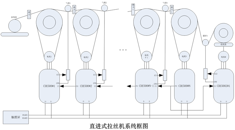
System Block Diagram
System composition
Inching
Winding control
Features
Threading
Before starting the machine, the front end of the raw material must be polished manually and passed through the mold step by step. In the field, the motor is generally driven to move at a low speed through a foot switch. At the same time, a tool is used to pull the wire from the front end of the mold to the rear end. After passing through the mold, the wire must be polished or pulled in order to be able to pass the next mold. Fine, only after passing the next mold. In this process link, the motor is required to have large and stable torque at the time of starting and low speed operation, and the running speed is stable, and the motor does not reverse when decelerating and stopping.
Brushed
After the mold is completed manually, the entire machine can be operated to achieve continuous stretching. The in-line drawing machine is usually controlled by a plurality of motors, and after a plurality of drawing dies, the raw materials are pulled to the required wire diameter at one time. In this process, it is required that the motor respond quickly, the tension of the wire is constant, and the tension balance bar fluctuates little, and the wire is not loosened.
Winding
The winding section is driven by a separate motor, and the stretched finished product needs to be wound synchronously around the spool. As the wire wound around the I-wheel becomes thicker and thicker, the motor speed is correspondingly slower. When the thickness of the rewind reaches the set value, the system provides automatic detection of shutdown. In the whole process, whether it is the start acceleration, stop deceleration or stable constant speed, the linear speed of the winding motor and the front-end motor is required to be synchronized, the wire is not loosened, and the rewinding motor is required to respond quickly. Accurate control.
Cable
Usually, the finished wire rod is wound on an I-shaped wheel. On the horizontal axis of the I-wheel, the wire rods should be arranged in a parallel and tight manner. In this process, it is required that there is a cable arrangement to complete the arranging of the finished wire rod from the upper end to the lower end of the horizontal axis. The reciprocating speed of the cable arranging device can be controlled at a fixed speed or according to the speed of the winding motor. According to the requirements of mechanical design, there are many solutions for the realization of cable, such as machinery, frequency conversion and so on.
Emergency stop brake
During the operation of the equipment, if an emergency occurs, the entire equipment needs to be stopped quickly. The process requires that the wire will not be broken after the shutdown process is completed, so that it can be ensured that the next time it can be started smoothly.
During the operation of the device, if the device detects a disconnection or other failure, the entire device needs to stop working immediately. A brake circuit can be provided outside the device. The brake output signal from the device controls the operation of the brake circuit so that the machine can quickly stop. Of course, you can also increase the braking resistor inside the inverter to control the rapid stop of the whole machine.
System composition
The system consists of N general-purpose inverters and a tension-specific inverter.
Each general-purpose inverter controls an independent motor, and the wire rod is stretched step by step through different molds. According to the principle of constant wire volume, as the wire becomes more and more thin, the wire will become longer and longer, which requires the rear motor linear velocity is higher than the front motor linear velocity. The main frequency of the previous stage motor is derived from the next stage motor. The inverter can use pulse mode or analog voltage mode to transmit the frequency of current motor operation.
The Nth motor runs at a fixed frequency. The frequency reference can be derived from the communication RS485 setting, external potentiometer or digital setting. The 1~N-1 motor uses the composite A+B frequency operation mode. The main frequency source At the subsequent operating frequency of the motor, auxiliary reference is derived from the PID control of the gas arm balance bar.
System composition
The arm is mainly used to sense the tension of the wire, and it is transmitted to the inverter through the AI ​​signal. The system uses the PID function to fine-tune the speed of the inverter. If the tension is too large, the inverter will properly reduce the frequency. If the tension is too small, the inverter will increase the frequency appropriately. This will make the wire drawing process more stable, and will not break the loose wire.
The winding motor is controlled by a special inverter for tension and supports the closed-loop adjustment mode with tension swing bar and the open-loop adjustment mode without tension swing bar.
The system controls the operation of the Nth motor through a DI signal, and the operation signal of the previous stage motor is derived from the operation state of the next stage motor. The operation signal of the winding motor is also derived from the operation state of the Nth motor.
Each inverter provides disconnection (fault) detection function. If the system detects a disconnection, it will immediately output a signal to the brake circuit. The brake circuit controls the whole machine to stop running. At the same time, the signal will be transmitted as an external fault. For each inverter. Break detection methods include PID feedback detection and DI signal input.
Inching
In order to manually insert the mold, the system supports the jog function. The user can achieve the speed of wearing through the setting of jog frequency (E0.00), jog acceleration time (E0.01) and jog deceleration time (E0.02).
Terminals are usually used to control the jogging. The user can set the X terminal function to forward jog or reverse jog.
The jog stop mode can be controlled by jog deceleration mode (E0.03).
Winding control
The system winding motor uses tension-specific inverter control and supports open-loop and closed-loop two different control modes.
Open-loop control mode
The winding inverter does not connect the tension arm balance bar. Tension control mode must be used. The user can set the tension on the line through the keyboard or potentiometer. As wire drawing progresses, more and more wires will be on the reel, and the diameter of the coil becomes larger and larger. According to T (torque) = F (tension) * R (reel radius), if the tension is constant, then As the diameter of the coil increases, so does the torque.
The system provides an automatic roll diameter calculation function, which can calculate the roll diameter according to the front line speed. The front line speed is the operating speed of the Nth motor. It is transmitted to the winding motor by analog voltage or pulse; the system can also be based on the thickness of the wire , The number of laps, and then calculate the cumulative number of laps according to the motor speed (pulse count or its own estimate), in order to calculate the winding diameter of the reel.
In order to better control the tension in the start, stop and acceleration/deceleration process, the system increases the mechanical inertia compensation coefficient, friction compensation coefficient, material density and other parameters to make the line tension constant.
Closed-loop control mode
The winding inverter is connected with tension arm balance bar, and the system can use tension control mode or VF/vector control.
When using the tension control mode, the control mode is similar to that of the open-loop tension mode. However, the system has one more PID closed-loop tension adjustment to ensure a more stable line tension.
If VF/vector control is used, the system can calculate the coil diameter according to the principle of constant line speed, V=f*PI*R, where V is the front-end linear speed, f is the frequency converter reference frequency, and R is the reel radius. At the same time, the tension arm balance bar is connected to the AI ​​of the frequency converter and closed-loop trimming is performed by PID. As the diameter of the coil increases and the line speed at the front end is stable, the reference frequency of the inverter becomes smaller and smaller.
When the coil diameter of the reel reaches the maximum coil diameter, the system can set the inverter to stop or continue to run.
The system provides the roll diameter reset function. When the user changes the roll, the current roll diameter can be reset to the empty roll coil diameter through a DI signal.
Features
With high work efficiency, the wire can be drawn into finished products at one time.
Low-speed jogging through the mold, stable operating speed, large torque.
Synchronous response speed.
The whole system only needs one tension special frequency converter, the other uses the general frequency changer, can reduce the cost greatly.
Special inverters for tension provide two different control methods, closed-loop tension control and open-loop tension control.
The roll diameter calculation function is provided to make the winding process more stable, and the tension swing swing is small, and the wire is not loosened.
Provides a variety of disconnection detection capabilities.
Provide roll diameter reset function.
Provide full roll stop function.
Clean Room Class,Iso 7 Cleanroom,Class 8 Clean Room,Iso Cleanroom Classes
Dongguan V1 Environmental Technology Co., Ltd. , https://www.v1airpurifier.com