introduction
Permanent magnet brushless DC motor is a new type of motor developed with the rapid development of rare earth permanent magnet materials and power electronics technology. With the rapid development of automotive electronic devices, the electronic control unit for vehicles is changing with each passing day. The application of electric motors in automotive electrical equipment is receiving more and more attention. Because of its wide speed range, small size, quick start, reliable operation, high efficiency and long life, people have begun to apply it to the development of automotive retarders.
This article is based on the research and development of 4 kW brushless DC motor installed in the car retarder, and introduces the use of VB 6. The O programming language implements the design of a permanent magnet brushless motor and derives experimental data.
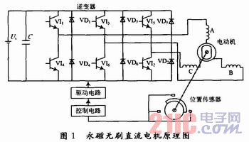
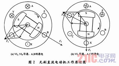
1 Basic principle of brushless DC motor The basic working principle of brushless DC motor is illustrated by the brushless DC motor system shown in Figure 1. The stator winding of the motor is a three-phase star connection, the position sensor is coaxial with the motor rotor, and the control circuit logically converts the position signal to generate a driving signal, and the driving signal is amplified by the driving circuit to control the power switch tube of the inverter to make the motor The windings of each phase work in a certain order. When the rotor rotates to the position shown in Figure 2(a), the signal output from the rotor position sensor is logically transformed by the control circuit to drive the inverter, so that VI1, VI6 (see Figure 1) are turned on, and A and B are two phases. When the winding is energized, the current flows from the positive stage of the power supply, flows into the A-phase winding through VI1, and then flows out from the B-phase winding, and returns to the negative pole of the power supply via VI6.
This article refers to the address: http://
The magnetomotive force Fa generated by the armature winding in space is as shown in Fig. 2(a). At this time, the stator and rotor magnetic fields interact to rotate the rotor of the motor clockwise.
When the rotor rotates through 60° electrical angle in space and reaches the position shown in Figure 2(b), at the same time, VI1 and VI2 are turned on, so that the rotor of the motor continues to rotate clockwise.
When the rotor rotates 60° electrical angle in space, the inverter switch will switch once. The conduction logic of the power switch tube is VI1, VI6→VI1, VI2→VI3, VI2→VI3, VI4→VI5, VI4→VI5. VI6→VI1, VI6. During this cycle, the rotor is always subjected to a clockwise electromagnetic torque and continuously rotates in a clockwise direction.
In the 60° electrical angle range of Fig. 2(a) to Fig. 2(b), the rotor magnetic field continuously rotates clockwise, and the stator synthesis magnetic field is not continuously rotated in space, but a jumping type rotating magnetic field. The distance is 60 ° electrical angle. When the rotor rotates at an electrical angle of 60° per space, the stator winding undergoes a commutation, and the state of the stator's combined magnetic field changes once. It can be seen that the motor has six states, each state has two phases conducting, and the conduction time of each phase winding is the time when the rotor rotates by 120 electrical degrees. This mode of operation is called two-phase conduction star three-phase six-state.
As long as the controllable transistors connected to the outlet ends of the respective phases are turned on and off in an appropriate order according to the different positions of the magnetic poles, the positional relationship of the magnetomotive force generated by the rotor coils at a certain electrical angle of the magnetic pole magnetomotive force is always maintained. The motor can be made to generate electromagnetic torque in a certain direction for stable operation. It can be seen that the motor can be reversed by changing the conduction sequence of the power transistors by means of logic circuits.
2 software design
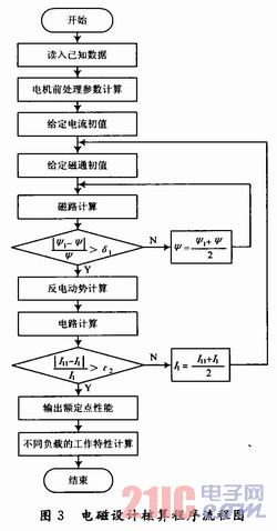
2.1 Main program flow chart In the motor design process, the most important problem is to solve a large number of curve charts. This routine uses interpolation method, fitting method and other methods to process a large number of formulas and curves, although it will produce small errors, but use It's quick and easy to save time. The main program flow chart is shown in Figure 3.
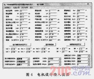
2.2 programming design interface using VB 6. O programming language realizes the motor design visual interface, quickly and accurately draws the desired data, saves time and improves work efficiency. As shown in Figure 4.
2.3 Programming The charts and curves used in the design of the motor, in addition to the calculation formula, some of the original formulas do not need to be calculated by interpolation, etc., the essence is to use the line between the two points near the interpolation point x The segment replaces the segment curve, and the function on the curve corresponding to x is approximated by the corresponding function on the line. Some of the program codes are as follows: 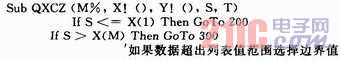
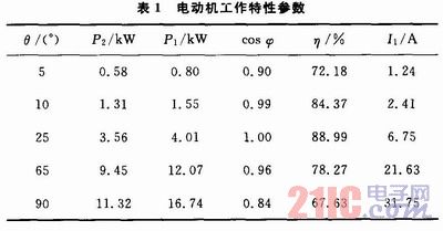
3 Experimental results This routine is a three-phase brushless DC motor with a power of 4 kW, a rated voltage of 208 V, a rated frequency of 26.5 Hz and a pole-to-number of three. According to the calculation, the motor operating characteristics are shown in Table 1.
4 Conclusion In this paper, a modern motor design method is used to design a vehicle retarder motor prototype. The performance index meets the technical requirements. Through the comparison of experimental data and design results, it is concluded that the brushless DC motor is used on the retarder. Practically feasible and efficient. The purpose of lightweighting and miniaturization of the retarder of the automobile is realized, which indicates that the application of the brushless DC motor on the retarder of the automobile is a future development trend.
Solid wire is based on the high end of the metal film capacitor market demand,the use of advanced production technology,with a better surface and inner quality and good stability,is a variety of film capacitor end of the iderl material,especially suitable for hig-end capacitor manufacturing.
Solid Solder Wire,Soldering Wire,Lead Free Solder Wire,Soldering Copper Wire
Shaoxing Tianlong Tin Materials Co.,Ltd. , http://www.tianlongspray.com