KPM-01 low-frequency therapeutic apparatus is a portable therapeutic apparatus suitable for family health treatment. The treatment principle of this therapeutic instrument is to simulate "acupuncture therapy", which has certain effects on the treatment of periarthritis of shoulder, low back pain, muscle sprain, relieve pain, and promote blood circulation.
The KPM-01 low-frequency therapeutic instrument adopts a pocket-sized portable structure. The power supply uses 4 1.5V batteries. The casing is equipped with a power switch, an output pulse frequency adjustment knob (adjustment range: 2 ~ 13Hz), and an amplitude adjustment knob (maximum pulse amplitude is about 100V) and output connecting wires. The two lead ends are respectively welded with round electrodes, and when used, the two electrodes should be symmetrically pasted on the skin on both sides of the affected part of the human body with self-adhesive tape. In addition, the therapeutic device also has the function of delaying the output of electrical pulses after starting up and automatically shutting down after 30 minutes.
The picture shows the electrical schematic diagram of KPM-01 low-frequency therapy instrument. The treatment instrument is composed of three CMOS integrated circuits as the main body, and forms a low-frequency treatment pulse generation and output circuit, a power-on delay output circuit and a 30-minute timer automatic shutdown circuit.
The low-frequency treatment pulse generation and output circuit are composed of the NOT gates 4, 5 and VT3, VT4, RP1, RP2, VD1 in IC1: CD4081 (four-two input AND gate integrated circuit), IC2: CD4069 (six NOT gate integrated circuit) It is composed of VD2, VD4 ~ VD6, and inductance coil L. Among them, the NOT gates 4, 5 of IC2 and R8, R9, RP2, and C3 constitute a self-excited oscillator. The pulse wave group output by the self-excited oscillator is a low-frequency treatment pulse source. Adjusting RP2 can adjust the treatment pulse frequency within the range of 2 to 13 Hz, and adjusting RP1 can adjust the voltage amplitude of the treatment pulse. The pulse wave of the self-excited oscillator output (IC2⑧ foot) passes through the RC circuit composed of RP1, R1, and C4, and is sent to the AND gates 1 and 4 for reshaping and amplification, respectively. Since the circuit parameter τ = (RP1 + R1) C4 is much larger than the treatment pulse width output by the self-excited oscillator, this circuit belongs to the RC differential circuit, and the width of the differential pulse can be changed by adjusting RP1. By adjusting RP1, IC1 pin 3 can output a continuously adjustable pulse signal with a pulse width of 0 ~ 3ms. When IC1 pin 3 is at "1" (high) level, VT3 is saturated and turned on; at IC1 pin 3 is at "0" (low) power. Usually, VT3 ends. As the VT3 is turned on and off, a therapeutic electric pulse with an amplitude of ≤100V and a frequency in the range of 2 to 13 Hz is generated on the self-inductance coil L, and is applied to the patient's lesion through two electrodes, which weakens nerve fibers. The pulse current stimulates to clear the meridians and treat diseases. At the same time, the pulse output by IC1 and gate 4 is reshaped and amplified by AND gate 2 to drive VT4. When IC1④ pin is "1" (high) level, VT4 is turned on, LED light indication (the amplitude of treatment pulse voltage varies with the brightness of LED, when the brightness is high, the amplitude of pulse voltage is also high); IC1④ pin is "0" ( Low) At the level, VT4 is turned off and the LED is off. The LED synchronously indicates the intensity and frequency of the treatment electric pulse. In actual use, patients can adjust the pulse amplitude and frequency according to their own feelings, and set the position of RP1 and RP2.
In order to prevent inadvertently setting RP1 at the maximum output position, causing the treatment pulse amplitude to be too large at the moment of start-up, the patient is suddenly stimulated and unable to adapt, the circuit has a special start-up delay circuit to ensure that the treatment pulse can be enabled after the start The amplitude is gradually increased, so that the patient has a process of gradually adapting from weak to strong. This circuit is composed of the NOT gate 6, C1, R2 ~ R6, VT1, VD1, VD2, etc. of IC2. When the power switch is turned off, C1 is shorted instantaneously, VD2 is turned on, so that VT1 is saturated and turned on, and the IC2⑧ foot output treatment The pulse (voltage part) is shorted to ground; at the same time, C1 passes R5 and the bases of VD2, R4, and VT1? Lai Shu? Therefore, the differential pulse width of the foot C1② narrows, and the treatment pulses output at both ends of L The voltage amplitude becomes smaller. As the charging voltage at both ends of C1 rises, the charging current becomes smaller, VT1 gradually exits the saturation region, and the differential pulse width input to IC1 ② pin gradually widens, and the amplitude of the pulse voltage output at both ends of L also gradually increases. Approximately 7 seconds after power-on, when the voltage across C1 is close to the high-level amplitude output by the IC212 pin, VT1 is cut off; the differential pulse whose pulse width is determined by the position of RP1 is input to the IC1 pin at the same amplitude, and the pulse output at both ends of L The amplitude also increases to the amplitude determined by the RP1 value, and the delay process ends.
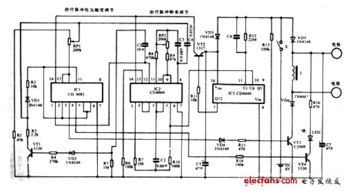
Figure KPM-01 electric principle diagram of low frequency therapeutic instrument
The 30-minute timer automatic shutdown circuit is composed of NOT gates 1, 2, 3, and VT2 in IC3 and IC2. Among them, IC3 (CD4040) is a twelve-bit binary serial counter integrated circuit, with 12 count stages, and each stage has an output (Q1 ~ Q12). There are also two input terminals, "CP" is the clock pulse input, and "Cr" is the clear input. When "1" level is added to "Cr" terminal, each output terminal is "0" level. When "Cr" turns to "0" level, under the action of the falling edge of the clock pulse, CD4040 makes an increment For counting, the maximum frequency division factor is 212 = 4096. The output end (Q12) of the 12th counting stage of IC3 in the figure ①foot controls the turn-on and turn-off of VT2. ①The pin outputs "0" level, VT2 is turned on, and IC1 and IC2 operate at a voltage of 6V; ①When the pin is at "1" level, VT2 is turned off, and IC1 and IC2 also stop working. When the switch S is closed, C6 is momentarily short-circuited, IC311 pin (clearing terminal) gets "1" level, ①pin (Q12) outputs "0" level, VT2 turns on, IC1, IC2 work because of 6V voltage , The square wave device composed of NOT gates 1, 2, 3, R7, R10, and C2 in IC2 works. The square wave pulse group output from the pin of IC2 ⑥ is input into IC3, and the frequency is divided by 12 steps. The timing starts. Treatment pulse output. After about 30 minutes, IC3's foot flips to "1" level state, VT2 is cut off, IC1 and IC2 stop working, no treatment pulse is output at both ends of L, and the treatment process ends. At this time, the patient can manually operate the switch S to cut off the power. Even if the patient fails to cut off the power supply in time, the static current of the therapeutic device after regular shutdown is only about 3μA, the power consumption is extremely small, and it is not harmful to the human body.
Vacuum Robot
Vacuum robot is floor Vacuum Clean Robot ,its smart and small robot cleaner,very convient and free use it. Robot vacuum with Intelligent planning path, memory family layout, cleaning every corner and WIFI connect mobile phone, Timing boot, Automatic Cleaning for Home and Office, Automatic charging.
Application:Vacuum Cleaning Robot use in home,hotel,office and other area.this robot vacuum clean floor,table,glass,dry and wet clean.
Vacuum robot with two facotry in china shenzhen and ningbo,welcome to visit facotry,we are 10years manufacture experience.
Vacuum Cleaner Robot Best sale ,export to many country. we are major in Vacuum Cleaner Robot Review.

Vacuum Robot
Vacuum Robot,Home Vacuum Robot,Floor Vacuum Robot Cleaner,Vacuum Robot With Water Tank, Vacuum Cleaner Robot Best,Vacuum Cleaner Robot Review
Zhengzhou Bangmi Smart Technology Co., Ltd. , https://www.cleanwindow-robot.com