This scheme combines the existing resources and gives a design example of the receiver. The implementation of the mixing part, the local oscillator part and the control part is analyzed and the specific circuit design is given. By using the spectrum analyzer and the RF signal generator to systematically test the design examples, the overall gain and noise figure of the system all meet the design specifications.
0 Preface
The Global Navigation Satellite System (GNSS) (GNSS (Global NavigaTIon Satel-lite System) has been widely quoted in recent years, which has attracted great attention in related fields. Current receiver modes are unable to meet the increasing demand accuracy requirements. Therefore, the development of a higher-precision, more stable and durable dual-mode receiver based on the original single-mode receiver has become the core of research.
This paper presents a design scheme for a GPS/Galileo dual-band dual-mode receiver RF front-end system. This scheme combines existing resources to demonstrate an example of such a receiver design. The functions and implementation of the mixing part, the local oscillator part and the control part are analyzed. Finally, the system is tested by the spectrum analyzer and RF signal generator to verify the correctness of the system structure.
1 GPS/Galileo dual mode dual frequency receiver system
1.1 Receiver structure
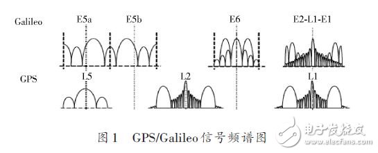
The first consideration for designing a receiver is the choice of frequency bands. As shown in Figure 1, GPSL1/L5 and GalileoE1/E5a ​​have the same center frequency. If this band is selected, many components can be reused, which greatly reduces R&D and production costs, and also reduces the receiver. volume of.
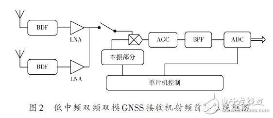
The structure of the RF front end of the more popular dual-band dual-mode receiver generally has three types of signal exclusive channels, common channels, and only one carrier frequency signal in the channel at a certain time. Based on the third scheme, this design strives to maximize the reuse of components while minimizing signal interference. The structure diagram is shown in Figure 2.
1.2 Receiver system overall performance indicators
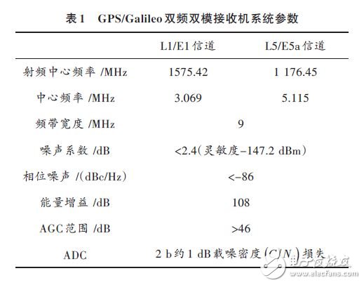
Based on the performance requirements of the reference receiver, the system indicators for designing the GPS receiver RF front-end chip are shown in Table 1.
2 GNSS receiver RF front-end chip selection
Considering the chip resources of the existing related devices in the market, based on the overall performance indicators and structure of the GPS receiver system, combined with the performance index parameters of each functional circuit module, in preparation for making the actual RF front-end circuit system using the selected chip. .
2.1 Low noise amplification section
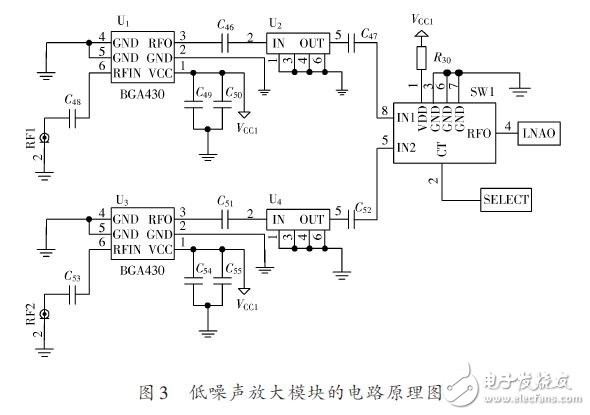
The low noise amplification part uses the BGA430 chip of INFINEON TECHNOLOGIES. The BGA430 chip is a broadband high-gain LNA chip. When the 5 V Power Supply, the gain of the chip in the navigation band can reach more than 28 dB, and the noise figure is below 2.4 dB. The noise figure of the low noise amplifier should be as small as possible, but the design difficulty and manufacturing cost of the circuit should be considered. Based on the above considerations, the BGA chip meets the requirements of the gain, NF and linearity of the system. Its circuit diagram is shown in Figure 3.
Ac Power Adapter,Ac 3 Amp Power Adapter,75W 48V 5A Power Adapter,Catv Power Adapter
Ninghai Yingjiao Electrical Co., Ltd. , https://www.yingjiaoadapter.com