Jacky Zhang
Summary
This article introduces a 10W LED drive power designed using TI control chip TPS92210. TPS92210 unique critical mode fixed peak current control function, the design does not require feedback, so the entire design is simple, fewer devices, and low cost.
introduction
Recently, in the LED drive power market, non-isolated solutions have become the hotspot of applications due to their smaller magnetic components, higher energy efficiency, fewer components, lower total bill of materials costs, and the ability to meet safety regulations with mechanical design . This article introduces a 10W LED drive power designed using TI control chip TPS92210. Using the unique critical mode fixed peak current control function of TPS92210, the design does not require feedback, so the entire design is simple, with fewer components, low cost, and high efficiency.
1. Introduction of power plan
This solution adopts the critical Buck circuit controlled by TPS92210, and sets the method of TPS92210 working at a fixed peak current to make the peak value of the inductor current fixed. Because the circuit works in the critical mode, the average value of the inductor current is equal to half of the peak current, thereby achieving a constant output the goal of.
At the same time, this solution does not require additional circuits, TPS92210 itself can achieve output overcurrent, short circuit, open circuit and other protection. Therefore, the whole scheme has few components and low cost.
The input uses a valley-filling circuit, so that the PF value of the whole machine has always been above 0.7.
C8, L2, and C5 form a pi-type filter. The whole machine passed the conduction test.
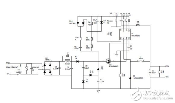
Figure 1: 10W LED power solution 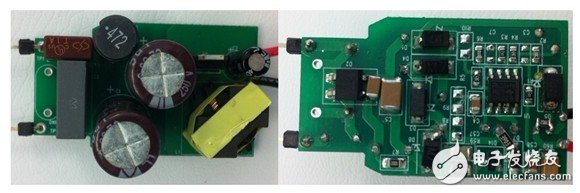
Figure 2: 10W LED power supply physical map
1.1 TPS92210 critical mode setting
TPS92210 needs to meet three conditions to start a new cycle:
1) The time from the last turn-on needs to be greater than the time controlled by the Ifb current.
2) The time from the last activation needs to be greater than the time limited by the chip's maximum frequency of 7.5us.
3) The Tze foot must have a zero crossing from high to low.
Since the above three conditions need to be met, the design connects the FB pin to Vdd through a resistor to set a fixed
The DC bias makes the opening of the TPS92210 completely determined by the voltage zero crossing of the Tze pin, which ensures that the converter always works in the critical current mode.
1.2 Inductor design
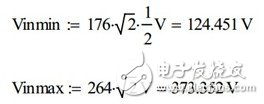
According to the input and output requirements, calculate the inductance. In this scheme, input 176V ~ 264Vac, output 40V, 0.25A. Since the input uses a valley-filling circuit, the input voltage range can be calculated as follows:
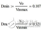
Based on the minimum and maximum input voltages calculated above, the minimum and maximum duty cycles can be calculated:
The average output current is 0.25A, the current works in critical current mode, and the average current on the inductor is the output current. The peak current and effective current of the inductor can be calculated as:

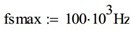
Because of the critical mode converter, the higher the input voltage, the higher the operating frequency. Taking into account comprehensive considerations, volume and efficiency, the maximum operating frequency is set to 100KHz.
Then the inductance can be calculated as follows:

So the inductance is about 700uH.
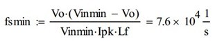
According to the calculated inductance, the minimum switching frequency can be verified as:
According to the calculated maximum duty cycle and the lowest switching frequency, the maximum on-time can be obtained as:

Tonmax is less than the maximum on time 5us allowed by TPS92210. So there is no problem with the inductor design.
Select the core: Assuming Bmax = 2500G, fill factor: k = 0.4 Current density: j = 6A / mm ^ 2 The AP value required for the core can be calculated as:

According to the AP value, choose RM5 as the inductor core:
The Ae area of ​​RM5 is as follows, the number of turns required for the inductor can be calculated:
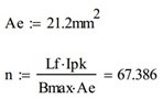
The inductance needs about 67 turns.
According to the previously calculated current RMS value and the set current density j, select AWG30 to wind the inductor.
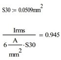
Use 1 strand AWG30 as the winding.
2. Test results
Based on the above analysis and design, a prototype was made and its performance was verified. The experimental results are as follows.
2.1 Efficiency test

2.2 PF value

2.3 Current accuracy

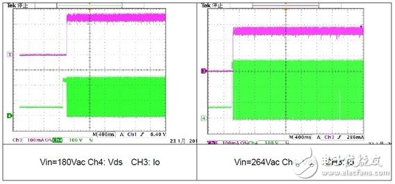
2.4 Start
2.5 Output ripple

2.6 Short circuit protection

2.7 Open circuit protection

2.8 EMC test

3. Conclusion
This paper analyzes and designs the critical mode buck converter controlled by TPS92210. The feasibility and setting method of critical mode of TPS92210 are analyzed. The calculation and design method of inductance are introduced in detail. Finally, a prototype was made to verify the correct analysis and calculation. The feasibility of using TPS92210 as a non-isolated constant current LED drive power is guaranteed.
PLC Splitters (Planar Lightwave Circuit) are single mode splitters with an even split ratio from one input fiber to multiple output fibers. Fiber Optic PLC Splitter counts are: 1x4, 1x8, 1x16, 1x32,1x64 etc. Fiber PLC Splitter is available with terminated or unterminated connectors as per your needs. Foclink Plc Fiber Optic Splitter family features the whole series of 1 x N and 2 x N splitter with boxes and modules. All PLC Optical Splitter provide excellent performance and reliability that meet GR-1221-CORE and GR-1209-CORE specifications.Foclink,a reliable supplier of fiber PLC Splitter is always beside u 7*24.
PLC Splitter
PLC Splitter,Fiber Optic PLC Splitter,Fiber PLC Splitter,Optical PLC Splitter
Foclink Co., Ltd , https://www.scfiberpigtail.com