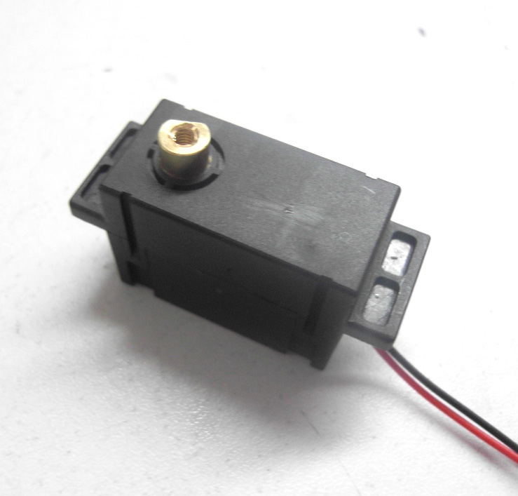
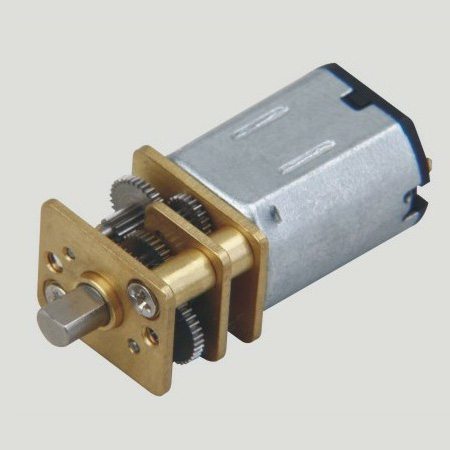
The Hall effect rotary position sensor uses a magnetic field instead of a mechanical brush or dial and is dedicated to measuring the angular position of moving parts. This product uses a magnetically biased Hall-effect integrated circuit (IC) to detect the rotational motion of the actuator shaft within the operating range. The principle is that the rotation of the actuator shaft changes the position of the magnet relative to the IC and causes the flux density to change, which is ultimately converted to a linear output.
This article refers to the address: http://
The internal magnetic field of the sensor replaces the mechanical brush or contact brush in the potentiometer, and the friction generated by the latter during operation tends to reduce the life of the device. As a result, the non-contact magnetic Hall effect technology used in this product line significantly reduces mechanical wear and actuator torque, extending equipment life. Hall effect rotary position sensors are used in a wide range of demanding applications in the transportation and industrial sectors and are cost effective.
Transportation industry application
1. Pedal position detection
In some heavy or other types of vehicles, Hall effect rotary position sensors can be used to replace the throttle cable. For example, the Honeywell RTY Series Hall Effect Rotary Position Sensor can be mounted on the side of the pedal to measure the extent to which the pedal is depressed. As the driver's pedaling force increases, the pedal depression increases accordingly, and more air and fuel are delivered to the engine, and the vehicle accelerates. When the driver releases the pedal, the Hall effect rotary position sensor senses a change in pedal position and sends a signal to the engine to reduce air and gasoline flowing through the throttle, and the vehicle decelerates. Cables can cause problems such as excessive stretching or rust, potentially increasing the burden of maintenance and recalibration. The use of sensors instead of cables will optimize the response of the engine control system, thereby reducing vehicle emissions, improving reliability, and preventing vehicle overweight. In general, electronic remote control systems are safer and more economical than older cable connection systems.
2. Suspension displacement / tilt position detection of passenger cars and trucks
The Hall effect rotary position sensor can be used in the height system of a passenger car or a heavy vehicle to sense the positional change of the suspension system. The passenger car's tilting system can lower the position of the upper structure and facilitate passengers to get on the bus. The Hall effect rotary position sensor can be used simultaneously on the operating and actuator ends of the system: a position sensor is used to detect the position of the joystick and a second sensor is deployed on the suspension arm or suspension arm connection to detect the vehicle height. Precise position sensing ensures that the vehicle is at the height required by the application system, making it easier to get on and off the vehicle. Large-capacity trailers can also use Hall effect rotary position sensors to detect the height of the trailer car to optimize the inbound process.
3. Speedboat tilt / draught difference position detection
The Hall effect rotary position sensor can be used to detect the speed/difference of the speedboat. This series of sensors accurately reports the angular position of the propeller, helping the driver avoid danger and improve hull performance.
*4. Application to electric bicycles
Honeywell sensors are also widely used in the electric bicycle industry. For example:
1. Hall on the electric car speed control
As the name suggests, the speed control is a speed control component of an electric vehicle. This is a linear speed control component with many styles but the same working principle. It is generally located on the right side of the electric vehicle, in the direction of the right hand when riding, and the rotation range of the electric vehicle handle is between 0 and 30 degrees. Common linear Hall components are available in AH3503 AH49E A3515 A3518 SS495. The AH3503 linear Hall circuit consists of a voltage regulator, a Hall voltage generator, a linear amplifier and an emitter follower. The inputs are magnetic induction, output and input. Proportional voltage. The quiescent output voltage (B = 0 GS) is about half of the supply voltage. When the S magnetic pole appears on the Hall sensor marking surface, the drive output is above zero level; the N magnetic pole will drive the output below zero level; the instantaneous and proportional output voltage levels determine the magnetic flux density of the most sensitive surface of the device. Increasing the supply voltage increases sensitivity.
Product features: small size, high precision, high sensitivity, good linearity, good temperature stability, high reliability. The output voltage of the Hall switch depends on the magnetic field strength around the Hall element. Rotating the handle changes the strength of the magnetic field around the Hall element, which in turn changes the output voltage of the Hall handle. The signals of the Hall handles used in electric vehicles are as follows:
Type of transfer:
Output voltage: Positive /5V power supply; Reverse /5V power supply.
Single Hall turn 1.1-4.2 (maximum) 4.2-1.1 (small amount);
Single Hall turn 2.6-3.7 (very few) 3.7-2.6;
Single Hall turn 1-2.5 2.5-1;
Single Hall turn 2.5-4 4-2.5;
Double Hall turn 0-5 5-0;
Photoelectric turn 0-5 (small amount) 5-0.
The vast majority of controllers currently on the market are products that recognize 1-4.2V turn signals. Reconstruct the output signal: Disassemble the rotary handle and change the polarity of the magnetic steel working surface inside the rotary handle to change the potential of the rotary output. If there are two magnetic steels in the handle, turn the two magnetic steels 180° and reinstall them. If there is only one magnetic steel in the transfer, take out the magnetic steel, reverse the 180°, and install the handle. This changes the starting position of the working magnetic field of the Hall element inside the turn, thereby realizing the transformation of the output signal of the turn.
2. Hall on electric brakes
The turn signal is a drive signal for the rotation of the electric vehicle motor, and the brake signal is a brake signal for the motor to stop rotating. The electric vehicle standard requires that the electric vehicle should automatically cut off the power supply to the motor when the electric brake is braked. Therefore, there should be a brake lever position sensing element on the electric brake lever. When the brake brake is actuated, the brake signal is transmitted to the controller, and the controller stops the power supply to the motor immediately after receiving the brake signal. The position sensing elements of the electric brake lever are mechanical micro-switches (both mechanical normally open and mechanical normally closed) and switch-type Hall sensing components (two types of brake low potential and high brake potential). The mechanical switch type has two leads, one for the negative pole and the other for the low-voltage brake controller. For a controller that supports a high-level brake, one is connected to +12V, and the other is connected to the wire. The three types of Hall-type lead wires are: brake line (thin blue +5V), negative pole (fine black), and the remaining one is broken wire. Common unipolar switch Hall element models are available in AH41/AH3144 / A3144 / A3282. Generally, the normally open brake signal is a normally high potential. When braking, the micro switch inside the brake is closed and its signal becomes low. Generally, the normally closed brake signal is a normally low potential. When braking, the micro switch inside the brake is opened and its signal becomes high. Generally, the brake signal of the electronic low-potential brake is a constant high potential. When braking, the Hall element signal inside the brake is turned over, and the signal becomes low. Generally, the brake signal of the electronic high-potential brake is a constant low potential. When braking, the Hall element signal inside the brake is turned over, and the signal becomes high. The change of the high and low potential of the brake signal is that the controller recognizes whether the electric vehicle is in the braking state, thereby judging whether the controller supplies power to the motor.
Door Lock Motor Characteristics 1. No direction: don't need to distinguish the door direction, left and right sides, both inside and outside the door, can be universal. (convenient purchase locks and reduce inventory).


2. Power: the power consumption is only equivalent to one 5 of the electric control lock, electric lock, 3 A magnetic lock power to open the door, often consumes 0.27 A. And spiritual lock unlock instantaneous current is less than 0.5 A, reduced the entrance guard, talkback host power consumption.
3. No collision: close the door without collision, reduces the choice of door closers requirements (not necessarily with 65 kg of door closers, door closers are free to choose to suit the door), to solve the building door because the door closers clash of the hydrodynamic force is too high, it is not easy to make the door more deformation, prolong the service life of the body.
4. The voice is light: close the door automatically locked, no noise, solves the noise due to electric control lock itself.
5. Life is long, life is up to 350000 times
Operating temperature range:
Mini Door Lock Motor should be used at a temperature of -10~60℃.
The figures stated in the catalog specifications are based on use at ordinary room temperature catalog specifications re based on use at ordinary room temperature (approximately20~25℃.
If a Lock Motor is used outside the prescribed temperature range,the grease on the gearhead area will become unable to function normally and the motor will become unable to start.Depending on the temperature conditions ,it may be possible to deal with them by changing the grease of the motor's parts.Please feel free to consult with us about this.
Storage temperature range:
lock motor should be stored ta a temperature of -15~65℃.
In case of storage outside this range,the grease on the gearhead area will become unable to function normally and the motor will become unable to start.
Service life:
The longevity of Door Lock Motor is greatly affected by the load conditions , the mode of operation,the environment of use ,etc.Therefore,it is necessary to check the conditions under which the product will actually be used .The following conditions will have a negative effect on longevity.Please consult with us should any of them apply.
â—Use with a load that exceeds the rated torque
â—Frequent starting
â—Momentary reversals of turning direction
â—Impact loads
â—Long-term continuous operation
â—Forced turning using the output shaft
â—Use in which the permitted overhang load or the permitted thrust load is exceeded
â—A pulse drive ,e.g.,a short break,counter electromotive force,PWM control
â—Use of a voltage that is nonstandard as regards the rated voltage
â—Use outside the prescribed temperature or relative-humidity range,or in a special environment.
â—Please consult with us about these or any other conditions of use that may apply,so that we can be sure that you select the most appropriate model.
when it come to volume production,we're a major player as well .each month,we rurn out 600000 units,all of which are compliant with the rohs directive.Have any questions or special needed, please contact us, we have the engineer group and best sales department to service to you
Looking forward to your inquiry. Welcome to our factory.

Door Lock Motor
Door Lock Motor,Mini Door Lock Motor,Door Lock Dc Motor,Door Lock Gear Motor
Shenzhen Shunchang Motor Co., LTD. , https://www.scgearmotor.com