The synthesized netlist file can be imported into PlanAhead, and then the key clocks and associated I/O ports can be allocated in PlanAhead. For example: PlanAhead can group certain logics, such as Gigbit Transceiver (GT), and associated I/O pairs, and then logically plan and allocate ports for these packets.
After the assignment is completed, PlanAhead can also perform DRC and WASSO verification on the completed design netlist to prevent planning errors.
Open a netlist-based project to complete the logical object layout and I/O port assignment.
1. Run [File] → [Open Project] in PlanAhead to open the following file.
PlanAhead_Tutorial/Projects/project_cpu_netlist/project_cpu_netlist.ppr.
2. Switch to the [Floorplan – io_planning_fp] window, run [Edit] → [Find...], open the search dialog shown in Figure 10-54, set as shown in the figure, and click [OK]. In the search results, click the [Cell] column twice, you will see the results shown in Figure 10-55, which shows the clock used in the project and high-speed I / O resources.
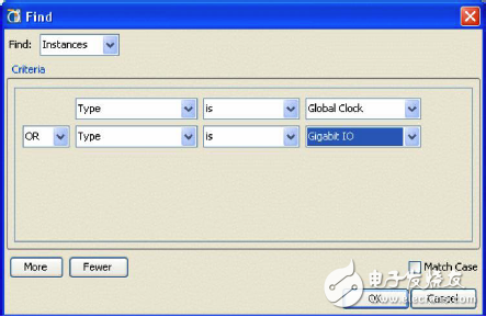
Figure 10-54 Finding the global clock and high-speed I/O
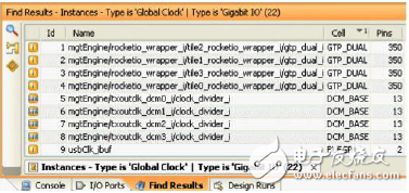
Figure 10-55 Finding results
3. Search again, set the search options as shown in Figure 10-56, and click [OK] to start searching. Figure 10-57 shows the search result. Select all the search results. You can see the specific position of the selected element in the device in the [Device] window, as shown in Figure 10-58.
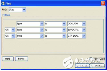
Figure 10-56 Finding the global clock and high speed IO
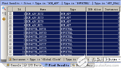
Figure 10-57 Finding results
![DCM, BUFG, GTP_DUAL position in [Device]](http://i.bosscdn.com/blog/06/11/35/N03_0.png)
Figure 10-58 Location of DCM, BUFG, GTP_DUAL in [Device]
4. Create a location constraint.
Select the Instance tab in the Find window, as shown in Figure 10-59. You can see the global clock and high-speed I/O resources used in the design. Select the button in the [Device] window to create a position constraint in Device. Select the first GTP_DUAL in the search window, hold down the left mouse button, drag and drop it to the GTP_DUAL area shown in Figure 10-60. When the mouse changes from a circle to a plus sign, it means finding a suitable position. Release the left button, which completes the position of an object. Place the remaining objects in the same way, including DCM and BUFG.
It should be noted that since DCM and BUFG are interrelated, when DCM and BUFG are placed, the associated objects are placed close together.
[Device] view of the position constraint
![[Device] view of the position constraint](http://i.bosscdn.com/blog/06/10/30/3318_0.png)
Figure 10-60 [Device] view of the position constraint
wzc , https://www.dg-wzc.com