In portable applications, the proliferation of wireless transceivers requires a focus on the ability to operate electronic circuits near high frequency radio transmitters. In a gigahertz radio system, close proximity of the radio antenna to the low frequency amplifier accessory can cause demodulation of the radio signal, resulting in destructive interference in the receiving circuit.
This article shows how to build a test platform using standard equipment used in most high-frequency analog labs. This test platform is suitable for testing and characterizing radio frequency interference (RFI) radiated in low frequency audio circuits. This test platform was originally used to check for Bluetooth applications with excessive noise problems at the output of the headphone amplifier. Although the noise caused by the Bluetooth transmitter is easily observed in the amplifier output, the frequency hopping RF combined with the complex coded modulation of the noise signal will generate an interference signal that is particularly complex and difficult to analyze. .
The test platform mentioned in this paper solves this problem by creating an interference environment that replaces complex Bluetooth signals with an RF scanning frequency modulated by a 1 kHz modulated signal. The 1 kHz modulated signal is used to track the RF input and the signal path to the audio amplifier output. This allows the user to observe the interference under conditions that are close to the RF carrier magnetic field strength, carrier frequency, and modulation frequency.
RF signal demodulationThe radio transceiver transmits voice and data signals by modulating a high frequency RF carrier. The sensitive circuit design near the antenna must be anti-interference or special protection against RF signal demodulation in the audio circuit. Layout and proximity to the transmitter may result in several different reception points on the board, causing interference at different frequencies.
Several studies, experiments, and calculations have shown the tendency of an op amp to demodulate an RF signal primarily at the emitter base junction of the input differential pair. Demodulation occurs even if the amplifier bandwidth is much lower than the RF out-of-band signal.
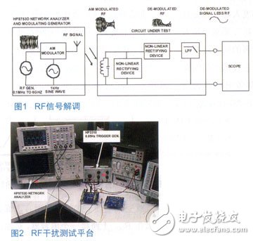
Figure 1 shows how the RF carrier is stripped and leaves a low frequency signal. Since the frequency of the RF carrier is many times higher than the bandwidth of the audio amplifier under test, the amplifier acts as a demodulator and filter, producing a carrierless low frequency replica signal of the modulated signal present at the output of the amplifier.
testing platformThe platform is capable of generating a swept carrier frequency from 100 kHz to 6 GHz with an externally modulated signal. The test platform for RF modulation is shown in Figure 2. The platform uses the hp8753d network analyzer as a variable RF carrier frequency and function generator to adjust the 1 kHz sine wave carrier frequency. The function generator (HP3310A) is inserted into the EXT AM BNC next to the HP8753D. The output of the network analyzer is connected to the sweep modulated carrier frequency of the simple antenna shown in Figure 3. The output power of the carrier frequency is adjusted to 0 dbm to match the standard Bluetooth signal. The synchronization between the frequency of the carrier and the time base of the scope is achieved by setting the scan time and scope of the network analyzer to 20 seconds and 2 seconds/zone, respectively. This results in a time base for the network analyzer and the scope of the 2 sec/zone. The direct frequency reading associated with the output voltage of the scope is achieved by simultaneously triggering a single scan on the network analyzer and scope (see Figure 5).
How to strip RF carrier and leave low frequency signalBy selecting the ability to individually modulate the frequency and RF carrier frequency and carrier signal level, various control experiments can be performed to classify the interference sources. Strict detection of the circuit conditions can be achieved by scanning the carrier frequency and measuring the modulated signal in the output of the audio amplifier circuit. Figure 4 shows the circuit schematic of the test board.
The output of the network analyzer is connected to the sweep modulation carrier frequency of the simple antenna shown in Figure 3.
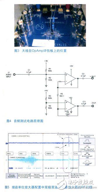
Figure 5 shows the frequency sweep results for a bipolar unity gain dual op amp. Radio frequency interference is ubiquitous at 3.9 GHz.
Interference on the output of Channel A and Channel B, using a fixed carrier frequency of 3.9 GHz and a 1 kHz 100% modulation
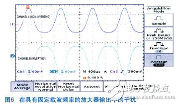
Figure 6 shows the interference at the channel A and channel B outputs, using a fixed carrier frequency of 3.9 GHz and a 1 kHz 100% modulation. The reason for choosing 3.9 GHz is because the maximum interference is achieved at this frequency. The signal shown is a 1 kHz demodulated signal under a unity gain dual operational amplifier. The asymmetry signal at 1 kHz is a modulated signal generated from a laboratory device, rather than from an amplifier.
Shenzhen Xcool Vapor Technology Co.,Ltd , https://www.szxcoolvape.com