Figure 1 presents the block diagram for the control of a DC brushless motor using an 8751 microcontroller. The P1 port of the 8751 is linked to a 7406 inverter to manage the commutation process of the DC brushless motor. Meanwhile, the P2 port is employed to capture signals H1, H2, and H3 from the position sensor. The P0 port is connected to a digital-to-analog converter.
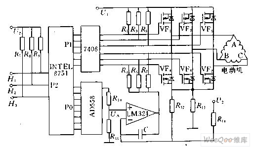
Figure 1: Schematic diagram of DC brushless motor computer control
Commutation Control
Based on the commutation mode of the stator winding, the states of the three rotor magnet position sensor signals—H1, H2, and H3—are first identified. The relationship between these states and the six power transistors is stored in tabular form within the EEPROM of the microcontroller. Using this table, the corresponding power transistor can be located based on the states of H1, H2, and H3, and then activated via the P1 port to achieve the commutation of the DC brushless motor.
Starting Current Limit
The resistor R13 is connected in series in the main circuit, such that Uf = R13 * IM, where the magnitude is proportional to the motor's current IM. The output voltage U0 of Uf and the digital-to-analog converter are sent to the two input terminals of the LM324 operational amplifier. When the feedback voltage exceeds Uf compared to the given signal U0 from the digital-to-analog conversion, the LM324 outputs a low level, disabling the three power transistors VF4, VF6, and VF2, thus cutting off all current paths in the stator winding of the DC brushless motor, forcing the motor current to drop. Once the current falls below Uf relative to U0, the LM324 output returns to a high level, allowing the main circuit to conduct again, effectively limiting the current.
Speed Control
In the normal operation of the DC brushless motor, the motor’s current can be controlled by regulating the output voltage U0 of the digital-to-analog converter, thereby controlling the motor's current. Specifically, the 8751 microcontroller calculates the rotational speed of the motor based on the period of the sensor signal and compares it with the given rotational speed. If the actual speed exceeds the desired speed, the output value of the P2 port is reduced, decreasing the motor current and slowing down the rotational speed. Conversely, if the speed is lower than the desired value, the output value of the P2 port is increased, thereby raising the motor’s rotational speed.
PWM Control Implementation
Speed control can also be achieved through Pulse Width Modulation (PWM). Figures 2 and 3 illustrate the use of PWM to control the speed of the DC brushless motor.
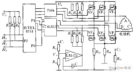
Figure 2: PWM control schematic
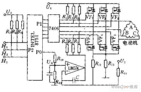
Figure 3: PWM control schematic
The direction of rotation of the brushless DC motor can be reversed by altering the commutation sequence. This is accomplished simply by replacing the commutation control table.
Volvo 50Hz Diesel Generator,Volvo 50Hz Diesel Generator,Volvo Diesel Generator Set,50Hz Volvo Generator
Shanghai Kosta Electric Co., Ltd. , https://www.generatorkosta.com