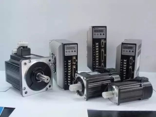
The servo system consists of a servo drive and a servo motor. The drive utilizes precise feedback mechanisms combined with high-speed digital signal processors (DSP) to control the IGBT, enabling accurate current output. This system is designed to drive three-phase permanent magnet synchronous AC servo motors, achieving precise speed control and positioning. Compared to conventional motors, AC servo drives are equipped with multiple internal protection features, and the absence of brushes and commutators in the motor makes them more reliable and easier to maintain.
To ensure the longevity of the servo system, certain considerations must be taken during operation. Environmental factors such as temperature, humidity, dust, vibration, and input voltage should be carefully monitored. It's essential to regularly clean the cooling and ventilation systems of the CNC unit and check that the cooling fans are functioning properly. Depending on the workshop environment, cleaning should be done every six months or quarterly to maintain optimal performance.
When CNC machine tools are not in use for extended periods, regular maintenance of the CNC system is necessary. The system should be powered up frequently and run at no load while the machine is locked. During the rainy season, it's recommended to power the system daily to generate heat from electrical components, which helps remove moisture from the cabinet and ensures stable and reliable performance of the electronics. Experience has shown that machines that are not used consistently often experience various failures after being restarted following wet weather.
Due to varying working conditions and limited technical support capabilities at the frontline, electromechanical systems often suffer from poor management, leading to shortened lifespans and reduced capacity due to equipment failure. This can result in significant economic losses for businesses.
A servo drive is a controller used to manage the operation of a servo motor. Its function is similar to that of an inverter used for standard AC motors. It is an essential component of the servo system, primarily used in high-precision positioning applications. Servo motors are typically controlled using three modes: position, speed, and torque, allowing for highly accurate motion control. As a high-end technology product, understanding how to test and repair a servo drive is crucial.
Here are some common issues and their solutions:
1. When checking the current monitoring output of the driver with an oscilloscope, only noise is visible and no readings can be obtained.
- **Cause**: The current monitoring output is not isolated from the AC power supply.
- **Solution**: Use a DC voltmeter to observe the output.
2. The motor runs faster in one direction than the other.
- **Cause 1**: Incorrect phase connection of the brushless motor.
- **Solution**: Check and adjust the correct phase.
- **Cause 2**: The test/bias switch is set to the test position when not in use.
- **Solution**: Move the switch to the deviation position.
- **Cause 3**: Incorrect setting of the deviation potentiometer.
- **Solution**: Reset the potentiometer.
3. Motor stall.
- **Cause 1**: Incorrect polarity of the speed feedback.
- **Solution**:
a. If available, toggle the position feedback polarity switch.
b. For tachometers, connect TACH+ and TACH- to the drive.
c. For encoders, connect ENC A and ENC B.
d. For HALL mode, reverse HALL-1 and HALL-3, then connect Motor-A and Motor-B.
- **Cause 2**: Encoder power loss.
- **Solution**: Check the 5V encoder power supply and ensure sufficient current is provided.
4. LED light is green, but the motor does not move.
- **Cause 1**: Motor is disabled in one or more directions.
- **Solution**: Check the +INHIBIT and –INHIBIT ports.
- **Cause 2**: No command signal reaching the driver.
- **Solution**: Connect the command signal ground to the driver’s signal ground.
5. After powering on, the driver’s LED does not light up.
- **Cause**: Insufficient supply voltage.
- **Solution**: Check and increase the supply voltage to meet the minimum requirement.
6. The LED flashes when the motor rotates.
- **Cause 1**: HALL phase error.
- **Solution**: Verify the motor phase setting switch (60° or 120°). Most brushless motors use 120°.
- **Cause 2**: HALL sensor failure.
- **Solution**: Check the voltage of Hall A, B, and C during rotation; it should range between 0 and 5 VDC.
7. LED remains red constantly.
- **Cause**: Fault detected.
- **Solution**: Possible causes include overvoltage, undervoltage, short circuit, overheating, drive disable, or invalid HALL signals. Check and resolve accordingly.
Neoprene Zipper Cable Sleeve,Neoprene Cable Management Sleeve,Zipper Sleeve Cable Wrap,Neoprene Wire Sleeve
Shenzhen Huiyunhai Tech.Co., Ltd. , https://www.cablesleevefactory.com