Abstract: In-depth study and analysis of low-light video enhancement technology, in order to solve the real-time processing capability of low-light video, combined with the technical characteristics of the Delphich platform to design an image enhancement system based on the TMS320DM6446 platform for low-light video real-time processing system to realize low-light video The system's real-time acquisition, real-time processing and real-time display module, and finally through the test processing results and real-time testing, the system design meets the requirements.
Keywords: Da Vinci platform; low-light video; data acquisition; embedded
O Introduction The low-light video system is more and more widely used in night vision technology. However, due to the low target illumination, the close target and background reflection coefficient, and the poor observation environment, the obtained low-light video image is always Not satisfactory results. Under the condition of China's existing hardware production capacity, the low-light image intensifier can not achieve the application effect, but the real-time image processing technology can quickly improve the image quality of the low-light system and increase the line-of-sight of the low-light video system. Combining real-time image processing technology with image enhancement technology has become an important development direction to shorten the gap between domestic and international low-light video systems. This paper implements a real-time processing system for low-light video on the DaVinci platform TMS320DM6446, which is a low-light video for China. System design has important reference value.
1 Low-light video enhancement technology The most notable feature of low-light video is that there is obvious random flicker noise superimposed on the image. By analyzing the characteristics and noise of the low-light video, the contrast and reduction of the low-light video can be increased. The low-light video noise is designed in two aspects to design a low-light video augmentation system. Due to the characteristics of the system, a simple and effective processing algorithm is required. Histogram equalization is a classical algorithm for increasing image contrast, and the algorithm is simple and the processing effect is good. The Gaussian smoothing algorithm can effectively remove the high-frequency components of the image and preserve the low-frequency components. These two algorithms are used in conjunction with the embedded processing platform. , can get very good results. This paper uses software design methods to achieve image enhancement techniques in design.
2 The micro-optical video system based on the DaVinci platform is characterized by real-time acquisition and real-time display, which realizes enhanced processing and denoising processing of low-light video, achieving real-time processing requirements, so it needs to be stronger. Real-time processing and data processing capabilities, here choose TI's DaVinci platform (TMS320DM6446) with DSP + ARM dual-core processing capabilities to meet the above requirements.
In the low-light video real-time processing system, the acquisition, processing and display process of the low-light video is performed by the CCD/CMOS camera or the image decoder on the TMS320DM6446 platform, and the low-light video is collected in real time and digitally converted and stored in the read buffer. The user can use the digital media processor of TMS320DM6446 to complete the real-time processing task of the low-light video, and display the processed low-light video through the display device on the embedded processing platform for real-time display. The principle of the low-light video real-time processing system is shown in Figure 1. 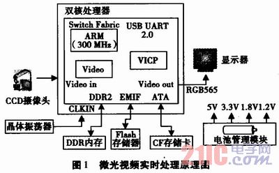
In the low-light video real-time processing system, the real-time acquisition part of the low-light video is completed by the video acquisition device and the video decoding chip; the real-time processing of the low-light video is completed by TI's TMS320 DM6446 dual-core processor; the low-light video real-time output system consists of The LCD display and video encoder are completed.
2.1 Acquisition of low-light video images The analog video digitization standard ITU-RBT. 656, it is at ITURBT. A new video digitization standard developed by 601 (CCIR-601). Since the CCIR656 video data stream uses 8 signal lines (19 signal lines are required in the conventional way), all image information and line synchronization, field synchronization, and even synchronization information can be transmitted. Therefore, the CCIR656 method is used for interface design, which facilitates real-time digital images. The processing hardware platform is modularized in units of functional units. 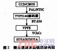
Acquired analog low-light video through CCD/CMOS video capture device, the video is PAL or NTSC, and the analog video passes the decoding chip TVP5146 and CCD controller BT. The 656 interface performs A/D conversion and converts the video into YCrCb format. At the same time, the collected low-light video is buffered in the read buffer of DDRAM or SDR-AM through an external memory interface (EMIF) for dimming. The video processing module processes the collected data.
2.2 The design of the low-light video processing function is based on the video format, and then the component is converted from the RGB format to the YUV format, and then the component is processed in the embedded processing platform, and the component is used instead of the Y component after the processing is completed. Converts a grayscale image into a color image for output and other operations. The structure of the video processing module is shown in Figure 3. 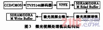
After the acquisition module collects a frame of low-light video, the video processing module acquires a frame of low-light video from the read buffer (Read Buffer) in the DDRAM/SDRAM, and sequentially performs enhancement and denoising processing on the low-light video, and processes again. It is cached in the Write Buffer in DDRAM or SDRAM for use by the display module.
2.3 Design of the low-light video display function In this system, we use Framebuffer technology and DaVinci's video processing subsystem VPSS technology to display the image. Framebuffer is a frame buffer, which is a driver interface in the Linux kernel. This interface abstracts the display device into a frame buffer. Users can think of it as an image of the display memory without having to care about the location of the physical memory, the page-changing mechanism and so on. Because these details are all driven by the Framebuffer device. The programmer simply displays the image to be displayed into the process address space and it is displayed on the screen. The structure of the display module is shown in Figure 4. 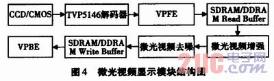
After the video captured by the acquisition module is processed by the processing module for enhancement and noise reduction, it uses the memory mapping method to display using FrameBuffer technology.
3 low-light video real-time processing system software design Because DM6446 integrates ARM and DSP dual-core, ARM terminal is the main control device, DSP side is used to process image processing, which greatly improves the processing power of the system. The system can be divided into three parts: the low-light video acquisition module, the low-light video processing module and the low-light video display module. The system starts to collect the low-light video by the video acquisition device, and the collected analog video image is passed. BT. 656 standard digitization, storing the digitized low-light video in the read buffer of SDRAM/DDBAM for use by the low-light video processing module; the low-light video processing module reads the low-light video from the read buffer and The video is preprocessed, the fitting component to be processed is extracted, and then the component is subjected to enhancement processing and denoising processing. After processing, the grayscale image is restored to a color image and written into a write buffer in SDRAMIDDRAM for display. The module performs display; the function of the low-light video real-time processing system is shown in Figure 5. 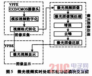
4 System Test The implementation part is tested on the DaVinci platform TMS320DM6446. Real-time processing is realized on the basis of real-time acquisition and real-time display. The results of each module test are as follows. The original low-light video captured is shown in Figure 6. 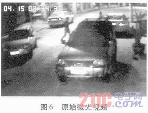
Figure 6 is an original image of a low-light video system. It can be seen that the image contrast is relatively low and there is particle noise on the surface. The real-time test results of video acquisition based on TMS320DM6446 platform are shown in Table 1. It can be seen that when the image processing algorithm is added, the video acquisition reaches 25fps, real-time requirements are met, CPU utilization and video in ARM and DSP. The bit rate is shown in Table 1. 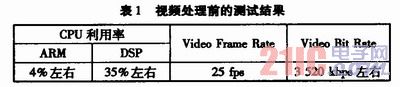
This article refers to the address: http://
Figure 7 is a real-time processing test of low-light video based on real-time acquisition. For the acquired one-frame low-light video, the image processed by the enhancement algorithm of this paper is used. 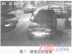
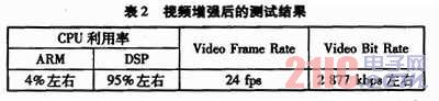
Figure 7 shows the enhancement effect of the low-light video. The real-time test of the low-light video processing is shown in Table 2. After the acquisition and processing, the video is displayed at a speed of 24fpe, which basically meets the requirements of real-time performance. The video bit rate is shown in Table 2.
From Figures 6 to 7 and Tables 1-2, it can be found that the system is enhanced in image processing capability and system CPU utilization compared to the original system, achieving the ability of the micro-light system to process.
5 Conclusion The DaVinci platform integrates a general-purpose processor and a digital signal processor dual core. Compared with the previous single-core processing platform, it has higher performance and lower power consumption, both in computing power and in control. Functionally, the requirements can be met. The design of the low-light system presented in this paper has important reference value for the design of related video processing systems.
Metal Core PCB , MCPCB Manufacturing Service
Resume
Metal Core PCB uses a base metal material as the heat spreader portion of the circuit board. Base metals in the MCPCB are used as an alternative to FR4 or CEM-3 boards for the ability to dissipate heat away from critical board components and to less crucial areas such as the metal heat sink backing or metallic core.
The metal core of the Thermal PCB can be aluminum (Aluminum Core PCB), copper (copper core PCB or a Heavy Copper PCB ) or a mixture of special alloys. The aluminum core PCB is most common.

INTRODUCTION
Conventional PCB use FR4 epoxy glass-based material on both sides of a board. However, with the growing popularity of light-emitting diode or LED technology, metal core Printed Circuit Board or MCPCB are being deployed to deal with the increased heat LEDs generate.
Today, metal core PCB are finding greater numbers of applications in the automobile industry, traffic light signal technology, in commercial buildings, shopping malls, and even inside homes.
MCPCB use either an aluminum or copper core with the bottom side of the board serving as the heat sink. MCPCB are also used to dissipate heat in intense power-generating analog circuitry.
Metal core PCB are connected through mounting holes and screws through a box build's chassis. In this arrangement, heat is not only dissipated through the metal core, but it is also transmitted to the chassis. Hence, an LED or analog device-populated board has a considerably larger surface finish for the purpose of dissipating that heat.
But here's a word of caution about using MCPCB – actually two things to be cautious about.
- One, you need to know that making an MCPCB is complex and complicated because a metal layer is laminated with FR4, a glass-base material. Therefore, the chemistry for lamination is different during board fabrication. There is a fair possibility that there would be voids underneath the lamination, if it is not bonded properly.
- Two, a fixture to dissipate the heat from the metal core needs to be carefully defined and designed. Both these concerns demand experience.

At JHYPCB, we've been doing this for a long time, as one of professional MCPCB/ Aluminum PCB manufacturers from ShenZhen, China. We can produce Metal Core PCB Prototype or aluminum PCB prototyping, aluminium PCB Board for led, No Quantity Requirements, and can successfully guide you through your next MCPCB project. We have worked with over half a dozen LED manufacturers over ten years and have seen enormous amounts of different applications using MCPCB.
Choose us to provide PCB Manufacturing services for you. Contact us immediately.
How Do Metal Core Circuit Boards Differ From FR4 Boards?

The dielectric material`s thermal conductivity is measured in Watts per meter, Kelvin (W/mK.) A 2.0W rating is fairly common; such material is approximately 6x-7x as thermally conductive as FR4. Best practice is to keep the dielectric layer as thin as possible. Doing so creates the shortest possible path from the heat source to the metal backing plate which is many times more thermally conductive than the dielectric material. Most of the materials come in a very limited range of thicknesses anyway, usually between .003" and .006". You won`t have all that much opportunity to specify something thicker that could diminish the effectiveness of the material at performing its thermal transfer function.
The metal backing plate used on the bottom side is the thickest element in the structure. It is available in several different thicknesses but it is best to use one of the three most common (1.0mm, 1.5mm, and 3.2mm) because they are the easiest to purchase without delays. The metal layer adds rigidity, keeps the circuit flat, and adds enough thickness so that the MCPCB can use the same mounting hardware that would be used for any other standard thickness circuit board. The metal plate side of the board does not receive any surface finish or soldermask.
Metal Core PCB Vs. Fr4 PCB Comparison

- Conductivity: FR4 has low thermal conductivity, typically around 0.3W, while MCPCB has higher thermal conductivity, ranging from 1.0W-4.0W, most commonly around 2.0W.
- Plated Through Holes: FR4 PCB typically uses plated through holes. Through hole components possible if required. In MCPCB, plated through holes are not available for 1-layer PCB. All components are surface-mounted.
- Thermal Relief: Thermal relief in FR4 PCB typically involves vias for heat transfer. Longer drill cycle, adds many processes. MCPCB materials provide their own thermal relief. Via drilling, deposition, and plating processes are eliminated.
- Solder Mask: FR4 PCB solder mask is typically dark colors (green, red, blue, black.) Usually applied top and bottom. MCPCB solder mask are almost exclusively white for LED boards. Applied to top only.
- Thickness: FR4 PCB has a wide range of thicknesses available using various material combinations and layer counts. MCPCB thickness variation is limited by available backing plate thicknesses and dielectric sheet thicknesses.
- Machining Process: FR4 PCB uses standard machining practices (drilling, routing, v-scoring, countersink, counterbore) while MCPCB uses the same machining as FR4, except that v-score must use diamond coated saw blades for the added strain from cutting into metal.
Material for Metal Core PCB

Metal Core PCB means the core (base) material for PCB is the metal, not the normal FR4/CEM1-3, etc. and currently the most common metal used for MCPCB manufacturer are Aluminum, Copper and steel alloy. Aluminum has good heat transferring and dissipation ability, but yet relatively cheaper; copper has even better performance but relatively more expensive, and steel can be divided into normal steel and stainless steel. It more rigid than both aluminum and copper, but thermal conductivity is lower than them too. People will choose their own base/core material according to their different application.
1. Aluminum PCB
Aluminum PCB , also, it is called Aluminium PCB, metal core PCB, MCPCB, IMS(Insulated metal substracte).
Aluminum PCB have 3 parts:
- Circuit Layer (Copper Layer)
- Dielectric Layer(Insulated Layer)
- Substrate Layer(Metal layer)
Aluminum Clad PCB
Available as 1 layer Non-Plated Through Hole (single sided), And 2+ layer Plated through Hole. Ideal application for LED lighting, power supply solutions. Aluminium Clad Benefits Include:
- Lower operating temperature.
- Reduce printed circuit board size.
- Increase power density.
- Extend the life of dies.
- Reduce the number of interconnects.
- Improve product thermal and mechanical performance.
- Combine power and control.
- Improve product durability.
- Enable better use of surface mount technology.
- Expedite heat sinks and other mounting hardware.
- Replace fragile ceramic substrates with greater mechanical durability
About Price:
- Price is based on the requirement of LED PCB
- PCB thickness: 0.6 – 3.0mm, always thickness more ,price higher
- Thermal conductivity: 1.0 – 10 W/m.k , thermal conductivity higher, price higher
- Material factory: Bergquist, Laird ETC, made in US factory that is more expensive than China.
2. Copper Core PCB

Copper core PCB is a copper substrate + Insulated layer + copper
Copper core PCB is a copper substrate + Insulated layer + copper circuits layer PCB, also, it is called copper substrate pcb, copper based pcb, copper clad pcb.
As a MCPCB manufacturer, we made various Copper core PCB for customers, Which used for High Power LED lighter ( 1000W+ ) and power supply.
In LED field, there are 4 types of Copper based Circuit Board.
COB Copper PCB(Chip on Board copper PCB)

Direct thermal path, no dielectric layer under the thermal path pad.
Direct thermal path, no dielectric layer,Aluminum-copper pcb.

The iron-based PCB use material for the base is from special steel, silicon steel and ect in stand of FR4 or CEM1 and can dissipate heat away from critical board components and to less crucial areas such as metallic core or the metal heatsink backing.
China PCB manufacturers becomes more and more professional on Iron-Based PCB.
The Iron-based PCB has all the functions as metal materical and the following particular characteristics:
- Vacancy area convenient for further machinery , procuring and fixing of the base ;
- High mechanic strength, good forther machinery suitable for the assembly heaven electronic parts on its surface;
- Silicon-steel is iron magnetic, and can be applied on micro-motors such as on VTR, FDD.
Metal Core PCB Thickness
The thickness of metal cores in PCB base plates is typically 30 mil - 125 mil, but thicker and thinner plates are possible.
MCPCB copper foil thickness can be 1 - 10 oz.
Benefits of Metal Core PCB Fabrication

Metal Core PCB Fabrication produces a product that transfers heat up to nine times more rapidly than a typical FR4 PCB. The laminates in MCPCB's dissipate heat which ensures that components which generate heat will remain cooler. This leads to a longer operating life as well as maximized performance for such components.
Applications of Metal Core PCB Fabrication

Although LED-based Solid State Light technologies have countless advantages, they inherently produce significant amounts of heat. This makes Metal Core PCB Fabrication helpful for applications like:
- General Lighting
- Automotive Systems
- Power Converters (industrial, telecom, power supplies, and high voltage regulators)
- Photovoltaic
- Street Safety (lighting, streetlights, etc.)
- Back Light Applications
Other applications that are ideal for MCPCB integration are solar panels and motion control applications. We can also combine metal core with our HDI PCB technology. We also offer other advanced circuit technology including Flexible PCB Rigid PCB , and Rigid Flex PCB .
Additional information
Metal Core PCB manufacturing process
Metal Core PCB Manufacturing Capability
LED Lighting and MCPCB (Metal Core PCB)
Understanding the Importance of Metal Core PCBs
METAL CORE PCB VS STANDARD CIRCUIT BOARDS
Metal Core PCB is the best source for the heat transformation
Are Metal Core PCBs the Solution to Your Thermal Management Challenges?
Metal Core PCB
Printable Circuit Boards,Metal Core PCB,Metal Core Led PCB,Metal Core PCB Prototype
JingHongYi PCB (HK) Co., Limited , http://www.pcbjhy.com