In the design of a new model of Hunan Changfeng Automobile Manufacturing Co., Ltd., according to the definition of the whole vehicle, the electric window has added the function of automatically closing the window and preventing the clip on the basis of the basic model. At the same time, it is required to use the existing parts of the basic model as much as possible in the design process, which can save development time and reduce costs. According to these requirements, this paper designs the new vehicle electric window control circuit and solves the design problem of the new vehicle electric window control circuit.
This article refers to the address: http://
1. Basic model electric window control circuit
When designing a new model, not everything starts from the beginning, but first selects a basic model as a reference according to the design requirements, which can reduce the design difficulty and make the design idea clearer. The design of the new model electric window is also carried out with reference to the basic model electric window. Therefore, it is necessary to introduce the function and control principle and mode of the basic model electric window.
The electric vehicle window control part of the basic model consists of the electric window main switch, the electric window sub-switch, the electric window motor, and the electric window motor breaker. The circuit diagram of the electric vehicle window of the basic model is shown in Figure 1.
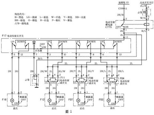
In Fig. 1, in the state where the ignition switch is in the ON position, the power window relay is closed, and the battery voltage is supplied to the power window control circuit through the fusible link 10. When the power window or main/snow switch (UP or DOWN) is pressed, current flows through the No. 8 fuse to the electric window motor. Thereby, the electric window motor receives electric energy and rotates, drives the window glass to move up and down, and the electric window opens or closes.
When the power window switch lock is pressed (in the OFF position), if the switch is operated, the other power window motors do not operate except for the driver's side window.
The basic model electric window motor has a circuit breaker to prevent damage to the motor due to overcurrent. The basic model electric window switch is a 1st gear switch, and the motor does not have an electronic control unit.
2. New model electric window control component function and circuit design
In order to achieve the anti-pinch function required by the new model and the function of automatically closing the window from the vehicle, the new model electric window motor must be controlled by the electronic control unit.
2.1. Power window electronic control unit
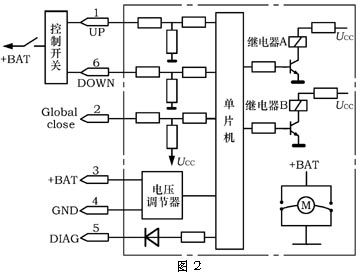
The principle of the electric window electronic control unit is shown in Figure 2. The main action of the electric window is the rise, fall and stop of the window. The rise, fall, and stop of the window are achieved by controlling the direction of the current of the electric window motor M or cutting off the current of the motor.
The direction of the electric window motor current or the stop of the current is achieved by the operation of the microcontroller A and the relay B. The MCU command is issued according to the control switch command or the anti-clamping force of the window glass or the signal from the central locking system that automatically closes all the windows. The voltage regulator is the 5.5V operating voltage required to adjust the voltage of the 12V system of the car to the microcontroller. The electronic control unit is integrated with the motor and each window motor has an electronic control unit.
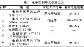
2.1.1. Electronic Control Unit Pin Definitions (Table 1)
2.1.2. Basic performance of electronic control unit
Operating temperature: -30 ~ 80 °C; storage temperature: -40 ~ 90 °C; working voltage: 9 ~ 15 V; quiescent current: <300 μA (25 ° C). pX2 car design network
2.2. Power window control switch
The electric window control switch can be divided into a 1-speed window switch and a 2-speed window switch, each of which has its own advantages and disadvantages, and can be selected according to actual conditions.
2.2.1.1 gear switch
The 1st window switch has 3 external pins connected to UP, DOWN and power (+BAT), as shown in the figure 3 of the figure. Among them, UP is the rising terminal, DOWN is the falling terminal, and +BAT is the positive pole of the power supply. When the switch is pressed in the UP direction, the UP terminal input is at a high level, and when the switch is off the UP terminal, the UP terminal is turned to a low level. Similarly, when the switch is pressed in the DOWN direction, the DOWN terminal input is at a high level, and when the switch is off the DOWN terminal, the DOWN terminal is turned to a low level, and FIG. 4 is a first-order switch signal diagram.
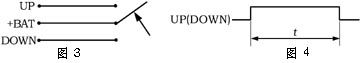
When the switch is pressed in the UP direction, t>300 ms, the window rises manually, and when t<300ms, the window automatically rises. During the automatic ascent, if the power window rise switch or the down switch is pressed, the window will stop automatically rising.
When the switch is pressed in the DOWN direction, t>300 ms, the window is manually lowered, and when t<300ms, the window automatically drops. During the automatic descent, if the power window up switch or down switch is pressed, the window will stop automatically descending.
2.2.2.2 gear switch
The 2nd gear switch is shown in Figure 5. There are 2 gear positions in either the UP or DOWN direction. For example, when the switch is pressed in the UP direction, first +BAT contacts the UP contact, and if it continues to press in the UP direction, +BAT contacts the two contacts UP and DOWN.
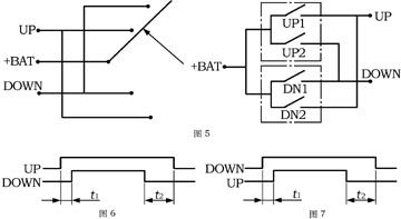
a. Ascend. When the switch is pressed in the UP direction, the UP contact first triggers a high level. If the button continues to the second gear position, the DOWN contact also triggers a high level. Here t1 is the mechanical delay between the 2nd gear contacts, t1 depends on the mechanical structure of the switch, usually a minimum of 5ms. T2 is the delay between the release of the button and the second and first gears.
b. Manual rise. As shown in Figure 6, when UP is high, it is manual lift. When the switch is released, if t2>150 ms, the motor stops and the window stops rising.
c. Automatic rise. Press the power window switch to the second gear, then both UP and DOWN are high. When the button is released, if t2<150ms, the glass will automatically rise. During the automatic ascent, if the power window up or down button is pressed, the glass stops rising.
d. Decrease (window opening). When the switch is pressed in the DOWN direction, the DOWN contact first triggers a high level. If the button continues to the second gear position, the UP contact also triggers a high level. Here t1 is the mechanical delay between the 2nd gear contacts, t1 depends on the mechanical structure of the switch, usually a minimum of 5ms. T2 is the delay between the release of the button and the second and first gears.
e. Manual drop. As shown in Figure 7, when DOWN is high, it is manual down. When the switch is released, if t2>150 ms, the motor stops and the window stops falling.
f. Automatically descend. Press the power window switch to the 2nd gear, then DOWN and UP are both high. When the button is released, if t2<150ms, the glass will automatically drop. During the automatic descent, if the power window up or down button is pressed, the glass stops falling. mPt car design network
From the above analysis, the 1st switch and the 2nd switch can realize the lifting function of the electric window glass, but they are technically different in realizing the lifting function.
The 1st gear lift and stop response time is longer than the 2nd gear switch, and the motor electronic control unit control software 1st gear switch is also more complicated than the 2nd gear switch.
The 2-speed switch has two signal inputs for rising, falling and stopping, and the signal is easy to recognize; the first-speed switch has only one signal input for rising, falling and stopping, and the input signal identification is difficult. However, the first-speed switch has a simpler structure and lower cost than the second-speed switch. The existing basic model uses the first-speed switch. Therefore, the new model decides to use the first-speed switch that the basic model has been used in batches, which can save development time and cost. In order to solve the relatively difficult problem of the 1st switch input signal recognition, the electronic control unit software has a 40ms anti-shake time for the rising and falling edges of the input signal.
2.3. Central control upgrade
The electronic control unit collects the boost pin to get a low level signal, and all windows will close until the window is completely closed. The centralized control boost signal comes from the central locking system. When the ignition switch is turned off and the central control door lock electronic control unit receives the signal from the remote controller or the door lock off, the central control door lock electronic control unit outputs a low level (<500mV) signal to the power window control unit to control the lifting. The pin, power window electronic control unit will control the entire window to be completely closed.
2.4. New model electric window control circuit
The electric vehicle main control switch and sub-switch, which are the same as the basic model, have the electronic control unit of the motor, and the new vehicle circuit with centralized control and lifting is shown in Fig. 8.
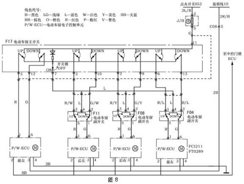
The new model of the electric window control circuit (Fig. 8) looks similar to the basic vehicle control circuit diagram (Fig. 1), but the control principle and method are completely different. The new vehicle control circuit cancels the electric window relay, which is mainly required for the window control and lifting function. According to the basic vehicle control circuit, after the ignition switch is turned off, the entire control circuit will no longer have power. If the new model is used in this way, the electric window electronic control unit will not work, and it will not be realized. The door lock electronic control unit automatically closes all windows after issuing the centralized control boost signal.
Therefore, the control circuit of the new model is changed from the battery to the electric control unit of the electric window through the fuse, which solves the problem of the control of the window.
The main window and sub-switch power supply of the electric window are controlled by the ignition switch. Only after the ignition switch is turned on the main power supply, the main switch and the sub-switch of the electric window have power supply. This design is considered for safety and power loss. There is a basic principle in automotive circuit design, that is, after the person leaves the car and the ignition switch is disconnected, the whole vehicle does not need to be charged, and the power supply must be disconnected. Due to the need for centralized control, the electric window electronic control unit requires power after the ignition switch is turned off. Therefore, the quiescent current is designed to be small when designing the electric window electronic control unit. Chapter 2.1.2 is introduced, 25 °C Less than 300 μA.
The power supply for the main switch and sub-switch of the new model is directly controlled by the ignition switch because the new model electric window has an electronic control unit, and the window up (UP) and down (DOWN) switches control the window rise and The falling command signal has a current of mA. The basic vehicle control circuit has an electric window relay, and the current flowing through the main switch and the sub-switch of the electric window is controlled by a small current passing through the ignition switch because the current flowing through the main switch and the sub-switch of the electric window is directly driven by the electric motor. The large current of the window motor, the ignition switch can not directly withstand such a large current, so the large current flowing through the main window of the power window, the sub-switch and the motor is controlled by the relay.
The new model is a small current command signal from the switch to the electric window electronic control unit, so the related wires are not as big as the basic model. The new model is designed as a 1mm2 wire, and the base model is a 2mm2 wire. Since the new model electric window main switch and sub-switch control the small current command signal, and the basic model electric window main switch and sub-switch control the large working current, the new model electric window main switch and sub-switch failure The rate is very low and the life is long.
The new model electric window switch lock uses the same switch as the base model. In the normal state, it is in the ON state, and after the switch lock is pressed, the switch lock is in the OFF state. When the switch lock is in the on state, the electric window main switch can control the front, rear, left and right four windows to work, and the electric window sub-switch can control the work of the side window. In the basic model electric window, when the switch lock is in the off state, only the driver side switch (left) can control the driver side window lift, and other windows cannot work. In the new vehicle control circuit, when the switch lock is in the off state, the driver's side main switch can control the front, rear, left and right four windows, while the sub-switch does not work.
3. The main technical parameters and functions of the new model electric window
In addition to the functions of ascending, descending, and centralized control (off-vehicle shutdown) described above, the new model of electric windows has the following functions.
3.1. Anti-pinch function
3.1.1. Anti-pinch function working conditions
After initialization, there is anti-clamp function when manually and automatically rising, and the number of anti-pinch is not limited.
3.1.2. Anti-pinch interval
From the lower edge of the upper seal strip 4 mm down, >200mm, <370 mm section is the anti-pinch section, as shown in Figure 9.
3.1.3. Anti-clamping force
At room temperature (22 ± 5) ° C, 80 mΩ line resistance, 14.5 V operating voltage, when measured with a 10 N / mm measuring instrument, the glass rising anti-pinch force <100 N.
3.1.4. Anti-pinch reverse distance
When the glass is manually or automatically raised, once it is blocked by the anti-clamping force, the rise is immediately stopped and the motor is reversed, and the reversal distance is 125 mm.
3.2. Power saving mode
After the input signal disappears for 120 ms and the motor temperature approaches room temperature 25 °C, the system automatically enters the power saving mode, at which time the module's quiescent current is <300 μA. When the motor control unit gets an input command, it is woken up.
3.3. Soft stop function
In order to prevent the glass from rising to the top or falling to the bottom, the motor is blocked by the impact and reduces the service life of the power window machinery. A soft stop function is required, and this function is provided when manually or automatically rising or falling. mPt car design network
3.3.1. Rising soft stop When the glass rises to the top, that is, at the rising soft stop point, the motor's power supply is cut off to stop working, and the glass is raised to the top by the inertia of the motor. This rising soft stop point is about 2 mm below the upper limit position. mPt car design network
3.3.2. Declining soft stop When the glass drops to the bottom, that is, when the soft stop point is lowered, the motor's power supply is cut off to stop working, and the glass is lowered to the bottom by the inertia of the glass falling. This falling soft stop point is about 12 mm at the lower limit position. mPt car design network
3.4. Overcoming obstacles
During the rising of the glass, if the glass has not reached the rising soft stop position and cannot rise normally due to obstacles, then within 2 s after the glass stops moving, press the lower opening key to drive the glass to the soft stop position, then Then, by pressing the rising key within 2 seconds to run the glass, the obstacle can be overcome to make the glass operate normally. There is no anti-pinch function during this ascent.
3.5. Motor protection function
Protective measures for the motor can significantly increase the service life of the motor and the entire power window system.
3.5.1. Motor stall protection
Within 250 ms of motor stall, the control unit shuts off the motor and stops the motor.
3.5.2. Motor temperature protection
After the control unit is powered up, if it is not initialized, the initial temperature of the motor is set to 80 °C; if it is initialized, the initial motor temperature is set to 160 °C.
Under normal circumstances, if the motor temperature reaches 170 °C, the input command is invalid, and the function is restored once the motor temperature is lowered. If the motor temperature reaches 190 °C, the motor is stopped immediately, and the function is restored once the motor temperature is lowered.
3.6. Self-diagnostic protection
In order to ensure the reliability of the system and improve the average time between failures of the system, self-diagnostic protection measures are adopted: if the power supply voltage exceeds 16 V ± 0.5 V, the electronic module turns off the automatic rising function.
3.6.1. Switch Contact Sticking When the switch contact is detected to have a sticking of up to 10 s, the input command is no longer received; if the switch contact is detected and then disconnected, the normal function is restored.
3.6.2. Relay contact sticking If the motor is blocked, the relay is detected to be turned on after the disconnection command is issued, then it is judged that the relay contact has been stuck, so the command is issued to turn the other relay on. Turn off the motor power. At the same time, the input command is no longer received until the relay contact is detected again to return to normal.
3.6.3. Hall element protection If the Hall element fails, the control unit can not receive the signal of the Hall element, then the control unit returns to the state before the basic initialization, that is, the distance can only rise up to 45mm when rising. At the same time, it does not have anti-pinch function.
3.7. System environment adaptive function
Since the system will be aging, the length of the steel wire and the looseness of the installation position after the long-term operation of the system, and when the ambient temperature changes and the friction changes, the system will use the adaptive function to ensure the system is reliable and safe. Work. The system will not lose data at any time, even if the motor is stopped when the power is suddenly turned off, the glass will automatically fall to the end when the power is restored. At the same time, the automatic function and anti-pinch function are restored.
4. Conclusion
The new model of electric window control circuit designed in this paper has been applied in the new model car jointly designed by the author and abroad. The electric window can work according to the design requirements, and the function is normal, which satisfies all the functions introduced in this paper. It will soon be put into mass production.
The J.SUN 4.1 Multimedia Speaker is a stereo system designed to deliver Home Theater sound. Compared to a 2.1 Multimedia Active Speaker System, 4.1 Multimedia Subwoofer Speaker System will provide the best listening experience, a 4.1 channel Multimedia Speaker will allow better enjoyment of music and movies with realistic sound. It need four stereo speakers and one subwoofer to play audio from connected sources. One of the significant benefits to using 4.1 speaker is that they are great for enjoying movies and music with better sound feeling, will be more realistic, attractive and crazy.
4.1 Multimedia Speaker
4.1 Multimedia Speaker,Multimedia Speaker,Multimedia Active Speaker System,Multimedia Subwoofer Speaker System
Guangzhou J.SUN Electronics Co., Ltd. , https://www.jsunaudio.com