Application of CAN Bus in Locomotive Monitoring System
This article refers to the address: http://
Taking the SJA1000 of Philips as an example, the characteristics of CAN fieldbus, the function and structure of the Controller and the basic content of CAN2.0B bus protocol are introduced. A train locomotive monitoring system based on CAN bus is described, and its system performance requirements. The system hardware construction, software design ideas and application results illustrate the advantages of the CAN bus and its general design process for industrial field control systems.
Keywords: CAN, fieldbus, SJA1000 initialization, locomotive monitoring system, signal detection, local area network
1 Introduction
For train locomotive monitoring systems, the speed, accuracy, reliability, and flexibility of data measurement/transmission are critical. The previous locomotive data monitoring only provided display and alarm of on-site data. Intelligent instruments were added to each device, which were scattered. It was not convenient to observe the locomotive operation and timely maintenance. The locomotive operation data could not be saved, and the data was to find out the locomotive. The cause of the fault and the important basis for maintenance; various operations of the smart meter, such as zero adjustment, limit, and accuracy, affect the display and alarm functions of the simple instrument due to environmental and human factors, and the work environment is harsh (high temperature, vibration, Electromagnetic wave radiation, etc., resulting in poor real-time and accuracy. With the development of domestic fieldbus technology, it is necessary to update the original detection system in time.
The locomotive monitoring system itself has dozens of data acquisition nodes (using a single-chip microcomputer AT89C51), and a higher-level industrial computer is responsible for data storage and recording. Because of the large number of collection points and high acquisition frequency (20Hz), the data on the bus is usually compared. Crowded, and the system has a very high requirement for the accuracy of data transmission and the real-time performance of alarm data. In view of this, we choose CAN field bus to build a data platform, which combines flexibility, real-time, accuracy and reliability. Advantage.
CAN is the abbreviation of Controller Area Net. It is a serial communication protocol developed by German Mercedes-Benz in the 1980s. It is mainly used for data communication between multiple control devices and multiple instruments. The road layer adopts the CAN2.0B protocol. It is now used in a wide variety of industrial applications, especially for systems that are optimized, analyzed and maintained. In the 1990s, domestic research on CAN bus applications began, and CAN bus technology has been applied in many fields.
This system is a LAN built according to CAN2.0B. The bus controller adopts SJA1000 of Philips Company of Germany, and the driver is PCA82C250 matched with it. The lower computer and the upper computer communicate in two directions through CANH and CANL twisted pair. The whole hardware structure of this system can be used as a standard node of CAN network to form a tree network, which is the minimum composition and typical application of CAN bus system.
2 CAN bus features
The biggest feature of the CAN bus is that each node in the network works in a multi-master mode. Each node can send information to other nodes point-to-point and point-to-multipoint at any time, regardless of master-slave, and has good flexibility.
The data transmitted simultaneously on the CAN bus adopts non-destructive arbitration, with small ID priority transmission and low priority data delayed transmission, which is effective for the network with heavy load to solve network defects, network congestion and improve efficiency.
CAN also has a strong verification function, and the error data is automatically retransmitted with high reliability.
In addition, the CAN communication medium selects the twisted pair cable, the space of the locomotive is narrow, and the field wiring, installation and disassembly of the twisted pair line are relatively simple. The maximum communication distance is up to 10km, and the bit rate can reach 1Mbps (when the communication distance is large, the bit rate will be reduced), and 16 messages can be transmitted simultaneously. Philips' SJA1000 has an operating temperature range of -40°C to +125°C and a storage temperature range of -65°C to +150°C.
For the SJA1000CAN controller selected by the system, its functional modules mainly include: Interface Management Logic, Receive FIFO, Receiveance Filter, Transmit Buffer and CAN Core Module ( CAN Core Block), the structure is shown in Figure 1 (see Philips Semiconductors: ApplicationNote - SJA1000 Stand-alone CAN Controller AN97076, 1997).
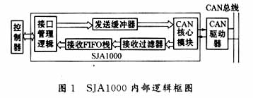
The interface management logic mainly handles the signal exchange with the microcontroller, and reads and writes data with the microcontroller through control signals such as CS, ALE/AS, RD, WR, and INT. The CAN core module is the execution part of CAN2.0B.
The receiving filter receives the data converted by the CAN core module, and performs filtering processing through an Acceptance Code Register (ACR) and an Acceptance Mask Register (AMR), and the data conforming to the ID requirement is received. The ACR provides the local ID, and the AMR provides the valid bit information for ID filtering. The receive FIFO stack is used to temporarily store data received through filter filtering.
The transmit buffer (TB) stores the data to be transmitted, and the CAN core module reads the data from the transmit buffer and transmits the data according to the CAN 2.0B protocol.
3 system functions and hardware implementation
In addition to the functions provided by conventional systems, this system also has functions such as adjustable module priority (ID adjustable), adjustable alarm limits, and saving alarm history data.
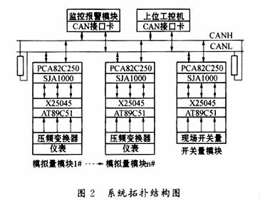
The work site consists of multiple analog meters and some switch signals. Each instrument is equipped with a data acquisition board. The acquisition of the switch is performed by a separate module similar to the analog acquisition board. The lower computer adopts ATMEL's AT89C51 micro-single-chip microcomputer, which mainly prepares communication data acquisition, simple judgment and data transmission; the communication part is composed of bus controller SJA1000 and its supporting driver PCA82C250, which can complete data link layer and physics All the work of the layer; another upper industrial computer, with 5M bytes of flash E2PROM, can provide 100,000 erases and 10 years of data retention period, used to store the data of each acquisition module before and after the alarm 1min, locomotive After each operation cycle, the data in the E2PROM is exported for future performance analysis; the monitoring alarm module is used for real-time display and alarm of data, in order to prevent the bottleneck phenomenon of the upper computer, the alarm task of each module is dispersed. Complete to the lower computer, send data to the upper computer only need to reset the alarm flag position; the bus terminal is connected with 100Ω ~ 120Ω resistor to suppress signal reflection, to ensure communication reliability. The twisted pair cable connects each module node to form a multi-master controlled LAN. In addition, in order to prevent the system from running unexpectedly, X25045 (the peripheral device of Xicor, USA, integrated Watchdog, reset controller, CMOS serial E2PROM array with block lock) is used as watchdog, 4KB SPI ( Serial Peripheral Interface) E2PROM can store some important data such as the alarm limit of this node. The system topology is shown in Figure 2.
4 Upper/lower computer data communication
SJA1000 supports the CAN2.0B specification protocol and has two working modes: BasicCAN and PeliCAN. This system uses BasicCAN.
Each AT89C51 MCU sends the data to the host computer every 0.05s. The CPU of the lower computer is not very busy with the host computer. Therefore, in order to prevent the external interference signal from causing the error alarm, the lower computer filters the data before sending the data. : 0.05s is divided into 5 acquisitions, and the average value is sent, so that false alarms of instantaneous high-frequency interference signals can be avoided.
The data sent by the upper industrial computer to the lower computer is generally for the command of a lower computer. The data received by the lower MCU is completed by the external interrupt INT0. The upper computer monitors all the lower-level single-chip microcomputers at the same time, and the lower-level computer also monitors the upper computer from time to time and receives the commands sent to them.
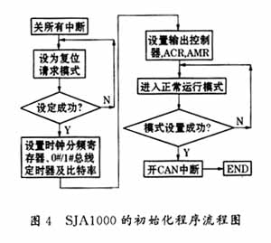
When the SJA1000 receives data in the BasicCAN mode, it is first loaded into the filter in the following order:
![]()
The upper eight bits of the ID are compared with the ACR eight-bit receiving code after receiving the AMR code mask, and the incoming code is received into the receiving FIFO, otherwise it is not received. Due to the higher priority of the ID in the CAN2.0B protocol, the ID highest bit ID10 can be set as the alarm data flag (this bit is zero when the data is over-limit) to ensure that the module data with alarm is transmitted preferentially. For the host computer, to receive all the data of the lower-level single-chip microcomputer, the upper eight bits of the ID should be completely shielded, and the lower three-digit ID2~ID0 are used as the upper-level industrial computer to send commands to the lower-level single-chip microcomputer (such as modifying the alarm limit, etc.). The flag bit, therefore, the limits of each module can be adjusted by the host computer to send commands during system operation.
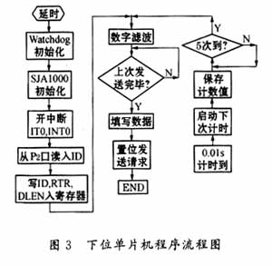
When the lower computer sends data, it first reads the limit value from the register to judge whether it exceeds the limit. If it exceeds the limit, ID10 is set to 0, otherwise it is set to 1. Then fill in the ID number of this module in ID9~ID3, the command position will be sent, then the MCU will not participate in the data transmission process, and other work will be completed by SJA1000 and PCA82C250. Since the ID can also determine the priority of the data, the MCU always reads the external 8-bit toggle switch as the ID from the P2 port, so that the priority of each module can be changed artificially, which enhances the flexibility of the system.
AT89C51 sends data to the host computer in the main program, receives the command of the host computer in the 0# external interrupt program, judges the meaning of the agreed command by the lower three digits of the ID, and will not elaborate here, only the main program and SJA1000 are given. Initialize the program flow, in which, at the beginning of each main program, in order to prevent the network from being unbalanced due to the time, acquisition cycle and software consistency of all lower-level machines, the workload of the upper computer is very large, and each lower-level machine At each reset, the main program deliberately arranges delays of different lengths of time, so that the time at which each module sends data can be evenly distributed.
After receiving the data, the host computer first checks the alarm flag bit to determine whether to alarm. If yes, writes the first 1 minute of data in the register and the corresponding time to the E2PROM, and continues to write the received alarm real-time data until the alarm. Stop one minute later. Otherwise, the data plus the current time is stored in the register in a queue, the register is full, and the oldest data is erased.
The monitoring alarm module receives data in the same way as the upper industrial computer, but each instrument module corresponds to one alarm device, n alarm devices display the over-limit status of each instrument in real time, and another LCD screen displays real-time data of the alarm module without alarm. Displays real-time data of the module with the smallest ID.
The above describes the basic process and principle of a single lower-level acquisition module and host computer communication. The whole system consists of several relatively independent, similar lower-level modules and a host computer. There is no communication between the lower-level machines.
5 Conclusion
This system was developed for a modified locomotive console of a company in Xi'an. After testing, software debugging and commissioning operation (20 acquisition modules), the performance is stable, the fluctuation range of the collected data is less than 0.05%, and the data transmission rate during test run is set. 125kbps, no data loss, no data transmission error between the upper computer and the lower computer, the highest bit rate up to 1Mb / s, anti-interference ability, high temperature resistance (-40 ° C ~ +120 ° C), data accuracy Satisfied, fully embodies the superiority of the CAN bus. Unfortunately, after the locomotive instrument alarm, the problem can only be solved manually.
In the next step, we will consider the communication between the upper computer and the secondary system on a higher level (the CAN field bus will still be used). If it can be realized, the problems of timely communication and monitoring of the communication and operation of the station and related departments with each train are Will be solved.
references
1 He Limin. MCU application technology selection. Beijing: Beijing University of Aeronautics and Astronautics Press, 1999
2 邬 明明. Microcomputer peripheral device practical manual - data transmission interface device volume. Beijing: Beijing University of Aeronautics and Astronautics Press, 1998
3 邬 明明. CAN bus principle and application system design. Beijing: Beijing University of Aeronautics and Astronautics Press, 1996
The PV Charge Controller works as a voltage regulator, its primary function is to prevent the Battery from being overcharged by the P.V array, being overly discharged by the load, or both.
Controller types:
• Single Stage controllers:
This type of controllers prevents battery overcharging by switching the PV array off when the battery voltage reaches the state of charge set point. The array and battery are automatically reconnected when the battery voltage reaches a lower value called the charge resumption.
• Pulse Width Modulation (PWM) controllers:
PWM controllers are the most common controller on the market today. These charge the battery by rapidly switching the full charging current on and off when the battery reaches a fully charged state. The length of the charging current pulse gradually decreases as battery voltage rises, reducing the average current into the battery.
Solar Street Light Controller,Solar Charger Controller,Programmable Controller,Light Controller
Delight Eco Energy Supplies Co., Ltd. , https://www.cndelight.com