In order to increase the comfort of the car, many cars are equipped with electric windows, and the driver can control the lifting of the door and window glass by pressing the button, which is very convenient. However, the window is not smart. If the driver does not pay attention to the member's hand or object sticking out of the window, it is easily pinched by the rising glass. For safety reasons, many passenger cars now use the Anti-Pinch Window Lifter (APWL). Europe and the United States have successively enacted legislation to determine APWL as the standard configuration for automobiles to improve driving safety and humanity. The Chinese government's legislation on APWL is also in the process of discussion. The existing APWL is equipped with a Hall element on the motor of the glass lifter to sense whether the motor is subjected to resistance or other optical sensors. This type of power window requires additional sensors to be installed in existing conventional glass lifters. In this paper, a window control module that can realize the window anti-pinch function based on the existing sensorless electric window is introduced.
This article refers to the address: http://
1 Principle of electric anti-pinch window
The electric anti-pinch window designed in this system consists of electric glass lifter and window control module.
The electric window regulator consists of an elevator part and a motor part. The lift part is generally of the sheave type, the gear arm type or the soft shaft type. The key to the electric glass lifter is the motor part. Generally, the reversible permanent magnet DC motor with built-in reducer is used. The motor has a magnetic field coil. By controlling the direction of the voltage applied to the coil, the forward and reverse rotation of the motor can be controlled. The window glass can be raised and lowered.
In the electric window control circuit of the basic model, the switch window and the relay are used to control the window motor, and the problem of adhesion is relatively easy to occur. In the system, the intelligent power driving device is used to control the window motor, and the direction of the motor is controlled by controlling the direction of the voltage applied to the DC motor. The change of current passing through the lifter motor completely reflects the change of resistance encountered during the rising or falling of the glass. By sampling the current passed by the glass lifter motor, the monitoring current can monitor the change of the resistance during the glass lifting process and perform the corresponding operating. The intelligent power drive device can realize the overcurrent, overvoltage and overheat protection of the motor, and automatically monitors the condition of the obstacle encountered during the rising of the glass by monitoring the current, and then reverses to prevent pinching. The functions that the control module can implement:
(1) Click the door control button (the button time is less than 300 ms), the window will automatically rise to the top or drop to the bottom, click any button of the same switch, the window will stop rising or falling;
(2) Delayed pressing the control window button (the button time is greater than 300 ms), the window rises or falls, and the button window is released during the ascending or descending process;
(3) When the window is running to the top or bottom position, it will stop automatically, and the window motor will be powered off;
(4) If the window glass is in the process of automatic ascent, it will automatically stop if it encounters a certain resistance, and it will effectively prevent accidental pinching of people or articles by dropping a distance.
2 hardware design principle of the window control module
Through the analysis of the national standard of electric glass lifter, the control object of the electric window control module is a permanent magnet DC motor with a supply voltage of 11 to 15 V, an operating current of no more than 15 A, and a stall current of not more than 28 A. The circuit of the door control module mainly consists of the following parts: power supply circuit, microcontroller part, electric window drive circuit, bus interface circuit, etc. The block diagram of the window control module is shown in Figure 1.
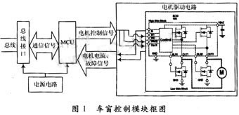
The microcontroller adopts the single-chip PIC18F2480, which integrates many very useful functions such as A/D, PWM, CAN controller, URAT, SPI and so on. The single-chip microcomputer PIC18F2480 is used to control the switching action of the power device, and the system status is monitored in real time, the fault feedback signal is received, and the fault information and button control information exchange between the central body controller and other door controllers are realized through the vehicle network. Displaying fault content on the user interface and real-time control of the door ensures driving safety.
2.1 Motor drive circuit design
The window motor is mainly composed of Freescale's intelligent power module MC33486 plus two MOSFETs to form an H-bridge to drive the bidirectional control of the motor. The internal resistance, temperature rise and voltage of the two MOSFETs are matched with the MC33486. The STB55NF06T4, D2PAK package is used. Its normal output continuous current is up to 10 A, the maximum peak current is up to 35 A, and the DC input voltage range is wide, up to 8 to 28 V. When the voltage is higher than 28 V, it has overvoltage protection function, for high-end and low-end. Both are capable of overcurrent protection, with a frequency of up to 30 kHz under chopping control, and mirroring of the detected high-end output current. These devices have provided comprehensive fault detection and protection, thus avoiding the use of excessive discrete components, greatly reducing module size and improving the EMC (electromagnetic compatibility) of the module.
2.2 Current sampling circuit design
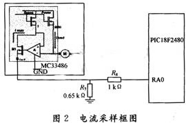
The anti-pinch function is mainly realized by monitoring the current change of the glass lifter motor, and its block diagram is shown in FIG. 2 .
Freescale's power chip MC33486 has a load-current linear replication function, the CurR output is proportional to the load current, and ILoad is the motor current of the glass lifter:
![]()
This current is converted into a voltage input to the sampling terminal of the microcontroller ADC through the sampling resistor R7 and the current limiting resistor R8. The voltage input to the MCU is:
![]()
The voltage is subjected to A/D conversion and some calculations to obtain the true current of the load. Therefore, monitoring the voltage input to the microcontroller port is equivalent to monitoring the current of the motor in the window motion. During the rising and falling process of the window, the current passing through the motor changes regularly when the resistance is encountered during the ascending process, and these current changes are reflected in the MCU by current sampling in real time.
3 software design of the window control module
3.1 Starting and stopping of the window
Start-up refers to the process in which the DC motor reaches a steady speed from rest. If it is directly started (ie, directly closed), and the U amount is added to the motor, the starting current Ia=(U-0)/Ra=U/Ra is large, which will bring a strong spark phenomenon, and the current is proportional to the torque. Excessive torque brings a large impact, and voltage fluctuations affect the stability of the power supply. When the system is designed, the motor starts by PWM. With a frequency of 2 kHz, it is divided into 10 segments, and the duty cycle is gradually increased from 0% to 100%. Each segment has 10 pulses for a total of 5 ms and a 10-segment startup time of 50 ms. It was confirmed in the experiment that with this kind of starting mode, the starting is relatively stable and the starting speed is better. During the period when the window is started, the current of the motor changes greatly, and the anti-clamp function cannot be realized by monitoring the change of the current. At the same time, the period is very short, so the anti-pinch function should be avoided during the period of starting.
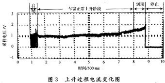
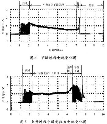
At the time of stopping, it is not stopped until the motor is blocked, but the motor is stopped when the current exceeds a certain range of its normal operating current. In this system experiment, the limit current is defined as 11 A. The current change of the motor in the ascending process is shown in Fig. 3. The current of the motor is gradually increasing. The continuous change, the change of the motor current in the falling process is shown in Fig. 4. The current shows a gradual decline and continuously changes.
3.2 Implementation of anti-pinch algorithm
In order to realize the anti-pinch function of electric glass, the designed window control module must include two functions:
(1) Must be able to judge whether an obstacle is encountered;
(2) After judging the obstacle, it must be able to determine whether the glass is rising or has risen to the top.
If the window control module determines that the glass encounters an obstacle during the ascent, the control module issues an instruction, the motor reverses, and the window stops after falling a certain distance; if the window control module determines that the glass has risen to the top, the control module A command is issued to stop the motor and the window is closed.
The current changes in the DC motor encountered when the window rises to the top and the window rises are shown in Figure 3, Figure 5.
By comparing Figure 3, Figure 5 finds that the motor current increases sharply from the normal operating current when it reaches the top and the resistance is encountered during the ascent. Therefore, it can be judged whether the current amplitude of the motor is monitored. Encountered an obstacle. However, the instantaneous current change of the motor may peak, so the amplitude must be the average value of the current over a period of time. When the current average A≥A obstacle (A normal
Only by the criterion of amplitude, it is impossible to distinguish whether the obstacles in the window are in the ascending process or at the top. By comparing Figure 3, Figure 5 finds that the resistance and the window rise to the top two during the window ascending. In this case, the speed of the motor current increases is not the same. When the window is in the process of rising resistance, the current becomes larger than when the window rises to the top. Therefore, it is possible to distinguish between the two cases by finding the slope of the current change. When f≥f resistance, the resistance is encountered during the rising of the window; when 0
In addition, an auxiliary criterion can be added to distinguish whether the obstacles in the window are rising or reaching the top. By comparing Fig. 3, Fig. 5 finds that the running time of the smashing window is different when the window starts to run and the resistance is encountered and the window rises to the top. When T>T top, the window rises to the top; when T≤T top, the resistance is encountered during the window rise. However, the different windows of the same model, because the installation can not be exactly the same, so there will be subtle differences in the top of the T, you can experimentally measure an initial T tip, record the time each window rises to the top, store to In the E2PROM, these data are used as the basis for adjusting the top of the T, so that the top of the parameter T is adaptive.
In this way, three sets of criteria are used to judge the difference between the two cases. When (A≥A obstacle)&&(f≥f resistance)&&(T≤T top), the resistance is encountered during the window rise; when (A≥A obstacle)&&(0T top), the window rises to The top. The use of three sets of criteria increases the accuracy of the judgment and reduces the false positive rate. Using these three criteria, the anti-pinch function of the electric window is well realized in the actual vehicle experiment, and the resistance window is lowered during the ascending process, and the current change is as shown in Fig. 5.
4 Conclusion
The PTC microcontroller PIC18F2480 integrates many functions on-chip, supports CAN communication and serial communication, and can be programmed online. The intelligent power driver MC33486 not only has a wide range of voltage inputs, large capacity, but also current mirroring. These two components are combined to monitor the obstacles encountered by the window by monitoring the current of the window motor. Based on the existing power window without the anti-pinch function, it is easy to add any sensor. The anti-pinch function of the electric window can be realized.
Dmx Led Bar 2722 is dmx512 rgb led lighting, width is 27mm and height is 22mm. DMX LED Bar 2735 is dmx512 rgb led lighting, width is 27mm and height is 35mm. We offer rgb led bar dmx lighting, similiar with american dj lighting or RC lighting, the LED Pixel Bar is Color Changing Light Bar. Led Rgb Bar , led rgbw bar is available. pixel bar have 1 led light bar, 2 led light bar, 3 led light bar, 6 Led Light Bar. It's dmx512 programming, the address have two type, one is auto address, another is manual address. That's to say we have led bar auto and led bar manual. Auto led bar, you don't need assign dmx address, it's convenience for event show and led light rental. Manual led bar, you need assign dmx address by Address Writer before light up, for DJ club, architecture light, it's ok. Maybe you want to know how to install a led light bar, don't worry, we have bracket, so that you can fix the bar easily. Regarding color changing led light bar, you can control by Led Controller.
Photo show of DMX LED Bar:

Dmx Led Pixel Bar,Dmx Led Bar,Dmx Light Bar,Led Rgb Bar
Shenzhen Iseeled Technology Co., Ltd. , https://www.iseeledlight.com