When developing a VoIP system, one of the main considerations is the interface to the analog phone. Designers must understand the telephone interface requirements that exist in the PSTN because they must be supported in VoIP systems. This article focuses on the two most commonly used interfaces to connect to standard POTS phones: Foreign eXchange Subscriber (FXS) and Foreign eXchange Office (FXO). Highlights some of the challenges designers may face when providing support for the analog telephone interface of VoIP cell gateways.
FXS and FXO are commonly used terms in the analog telephone field. Why are they so important for VoIP applications? For traditional telephone connections on the PSTN, the central office exchange provides power and the phone rings. The phone itself provides a tip / ring circuit to request service or answer a call from the PSTN. For calls made via the Internet, the FXS circuit will simulate the function of the telephone exchange at the central office. The community gateway is virtually a switch, providing power to the phone and ringing, and detecting loop current. On the other hand, the FXO circuit simulates the telephone function, provides loop closure function and detects incoming ringing.

Figure 1 Line echo from two-wire to four-wire conversion
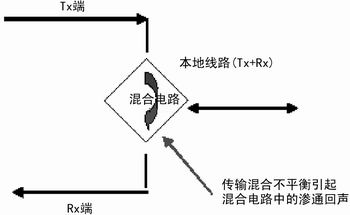
Figure 2 Local loop line echo
Analog phone and PSTN interface
The FXS circuit includes two parts: CODEC and SLIC (Subscriber Line Interface Circuit). CODEC consists of ADC and DAC. The ADC converts analog signals from analog phones into digital signals that can be transmitted over VoIP networks. The DAC converts digital signals to analog levels to drive analog phones. In order to achieve 4kHz audio bandwidth, the sampling rate of ADC and DAC is usually about 8kHz. The SLIC device simulates the PSTN voltage level. It must detect whether the phone is on-hook or off-hook and generate a ringing voltage of up to 120V.
FXO circuit includes CODEC and data access device (DAA). CODEC has the same function as FXS, converts analog voice into digital signal, and then converts it back. The DAA analog (POTS) telephone function, whose important role is to remove high-voltage DC bias, close the PSTN loop, and thus only transmit analog AC signals from the PSTN.

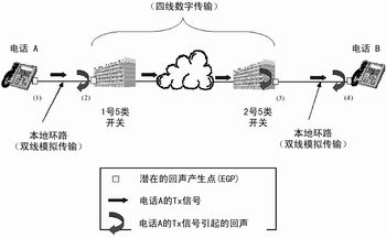
Figure 3 PSTN switching / transmission network
FXO mirror FXO
In the VoIP gateway, the FXS circuit is the basic interface for establishing outgoing calls and receiving incoming calls on the packet network. In the central office application, the two-line SLIC interface on the POTS line card functions as the FXS interface. In customer premises (CPE) applications, FXS circuits are present in the gateway, providing dial tone, battery current, and ringing voltage functions, and detecting loop closure from the phone. Since the switching function is at the CPE level, there is no need to establish a direct connection with the PSTN. However, sometimes it is useful to use the FXO interface to establish a connection to the PSTN. This is the same type of interface that ordinary POTS phones connect to the central office, but there are some improvements. Important uses of the FXO port include:
• Important communication lines during power outages: if the voice gateway is out of power, the gateway cannot connect to the packet network and cannot make or receive calls. In this case, a relay can be used to connect the analog phone directly to the PSTN. If this happens, the FXO circuit is very intelligent and can detect ongoing calls, thereby avoiding call interruption when power is restored.
Call redirection: When the packet network cannot be used due to network congestion, the FXO circuit can remember the number dialed by the user and send the call to the PSTN through the FXO circuit to complete the call. This method eliminates the need for customers to redial the phone number when a packet network fails.
Remote VoIP calling: When VoIP customers are not at home, they can still dial their home number through the PSTN network to make VoIP calls. The voice gateway receives the call through the FXO port and forwards it to the VoIP network.
User feed function in the FXS line feed interface: The complementary function in the FXO interface is the battery sink. The tip wire of the central office and the ring wire are connected via the FXO off-hook relay, and FXO provides current limiting.
Overvoltage protection: FXO must provide overvoltage protection due to possible exposure to lightning and electrical interference. The tip of SLIC and the ringing input in the FXS circuit have been carefully designed to provide additional overvoltage protection.
Ringing: Ringing is provided by the central office, but FXO must be able to detect ringing and forward this information. The FXS circuit must provide ringing to the phone. The low-voltage ringing signal generated by CODEC or SLIC is amplified by SLIC, and the phone rings through the local loop.
Signaling: Signaling means that FXO can receive on-hook / off-hook information and provide off-hook instructions to the central office as required. It must also detect ringing and other conditions and transmit relevant information. FXS must be able to detect on-hook / off-hook status, detect and generate DTMF tones and caller ID signals.
Coding: Coding is one of the functions of CODEC device, which is part of the interface between FXS and FXO. It refers to the analog-to-digital coding and digital-to-analog coding of speech signals.
Hybrid functions: Hybrid functions are essential for stability and high-quality voice, as are FXO and FXO interfaces.
Echo Whether making a call through the PSTN or packet network, stability and high-quality voice are critical. The potential impact of echo is also critical to the interface function of FXS and FXO. The impedance of ordinary POTS telephones between 200W and 400W is relatively uncontrolled. Since the current from the local end to the user is two-wire, and the gain does not increase, the impedance change encountered usually does not affect performance. However, if the carrier communication system uses a two-wire to four-wire audio mixing circuit at each end, stability and line echo problems may occur, and four-wire channel gain may also occur.
The line-echo is caused by the through-though delay of the transmission of the voice signal to the receiving channel at the mixed (two-wire to four-wire transition point) end, or the reflection of the local loop due to impedance mismatch. There is always line echo in the PSTN, but it is not necessarily a problem. In fact, part of the telephone transmission signal will be coupled to the receiving channel to generate sidetones, so that the speaker can hear his voice in the receiver. Without a side tone, the speaker is unclear whether the other party can hear himself, and the conversation may be quite awkward. However, if it is not controlled, the excessive line echo will affect the calling user's call experience in the following two aspects:
? The greater the echo, the greater the interference during the voice call. Although in many cases, there is a low echo on the line, but the user will not notice it.
The delay time of the echo will greatly affect the voice quality. Delay refers to the time between the user speaking and the user hearing their own echo. If the round-trip echo delay is greater than 25ms, the voice quality will be affected.
The hybrid circuit completes the two-wire to four-wire conversion, and vice versa, and its main function is to limit the amount of output transmission signal that "penetrates" into the receiving channel. Due to the transmission imbalance (hybrid components are not ideal, impedance mismatch, etc.), always a certain amount of Tx signal will enter the Rx channel (see Figure 1).
In addition to transmitting the echo generated by the mixed unbalance, the impedance mismatch of the mixed terminal will also generate line echo. If the characteristic impedance of the line termination is incorrect, an echo will be generated. The incoming signal of the two-wire local loop encounters the mixed termination resistance and is reflected back to the line, which produces echo (see Figure 2). If the terminal is not properly connected to CPE equipment (such as a telephone or modem), it may also generate echo in the local loop.
In order to better understand the source of the echo, you also need to know some PSTN background information. The telephone network consists of two basic parts: the switching and transmission core, and the local loop.
The exchange and transmission part is responsible for transmitting and routing calls, call services, dunning, etc. In this part, all voice and data signals are transmitted digitally, and Tx and Rx signals use different channels. This makes the transmission of long-distance signals more convenient, and repeaters and microwave transmission towers can also be used. The local loop includes "last mile" copper wire, which realizes the connection between the central office and users.
Tracking the Tx signal of phone A in Figure 3, assuming that the echo generated by EGP is very large, it can be seen from the figure that phone A generates echo in three places (EGP 2, 3, and 4). The echo at EGP 2 is caused by the line's mixed impedance mismatch and causes the echo to return to phone A. Since the round trip delay is not very long, the echo is not a problem, and the end user will not notice it. Sometimes sidetones can also mask this echo. The echo that caused the problem was generated at EGP 3 and 4 because its round-trip delay is quite large (greater than 25ms). The echo generated at the far end of the network has the greatest impact. The echo at EGP 3 is due to transmission mixing imbalance, while the echo at EGP 4 is caused by the impedance mismatch of the phone connected to the line.
To eliminate harmful echoes, telephone service providers generally install echo cancellers in the PSTN. In order to cancel the echo on the telephone A connection, the echo canceller should be installed just before or within the No. 2 category 5 switch and plugged into the four-wire part of the network. The role of the echo canceller is to model the echo characteristics of the local loop part that contains EGP 3 and EGP 4, plus the knowledge of the Tx signal of telephone A, it can be eliminated before transmitting the Tx signal of telephone B back to telephone A EGP 3 and EGP 4 echo. In a VoIP system, for calls made and terminated by a VoIP CPE gateway, the echo must be completely handled in the VoIP gateway. For calls that must be routed to the PSTN, the PSTN will continue to handle echo cancellation.
Standards Although making VoIP calls over a packet network does not require a direct connection to the PSTN, this does not mean that system designers can ignore PSTN requirements. VoIP cell gateway designers must understand the existing telephone technical requirements and apply them to the system's FXS and FXO interfaces. For understanding the behavior and requirements of PSTN, the following four standards are essential:
1. GR57 specifies the behavior of the digital loop carrier communication system from the local tip / ring pair to the system user tip / ring pair.
2. TA909 describes the behavior from the optical fiber at the local office digital interface (T1 in North America) to the tip / ring interface of the system user terminal to the roadside system. Fiber to the roadside system is usually a 16 ~ 24 channel system.
3. GR303 discusses the behavior of integrated digital loop carrier communication systems. The behavior from the T1 digital interface to the system user terminal tip / ring interface is specified. Such systems usually have a large interface with hundreds of tip / ring pairs on the user side.
4. GR1089 specifies environmental standards for North American telephone infrastructure, including lightning resistance, power supply crosstalk immunity, and EMC. It also sets limits for accidental RF emissions.
Conclusion As people ’s interest in VoIP services continues to increase, phones specifically designed for making voice calls over packet networks (that is, IP phones) will eventually replace standard analog POTS phones. But before that, designers of VoIP gateways must consider how to connect their equipment to the above-mentioned standard analog phones. FXS and FXO circuits provide an effective way for this.
Xinxiang Mina Import & Export Co., Ltd. , https://www.mina-motor.cn