RF2514 is an AM / ASK VHF / UHF transmitter chip integrated with a phase-locked loop. It can work in the 100MHz ~ 1000MHz frequency band and uses the AM / ASK modulation method. The chip contains integrated voltage controlled oscillator, phase discriminator, frequency divider, reference crystal oscillator and phase locked loop circuit,  Able to transmit digital signals. In addition to the standard low-power mode, RF2514 also has an automatic blocking function, when the PL loses lock, the transmitter output is invalid. The power supply voltage of RF2514 is 2. 5 ~ 3.6V, can provide + 1dbm output power to 50Ω load. RF2514 adopts QSOP16 package, and has the characteristics of small size (4mm & TImes; 4mm), low price, good performance, etc. It is suitable for the application of VHF / UHF ISM band in the United States and Europe.
1 Pin function of RF2514
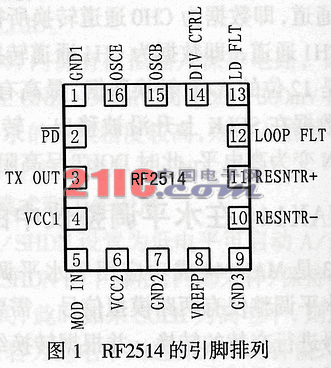
The arrangement of the pins of RF2514 is shown in Figure 1. The functions of each pin are as follows:
Pin 1, 9 (GND 1, 3): Analog ground. For best performance, use short printed wiring to connect directly to the ground plane.
Pin 2 (PD): low-power mode control terminal. When PD is low, all circuits are turned off. When PD is high level, all circuits are turned on.
Pin 3 (TXOUT): transmitter output. The output is a transistor open collector (OC) method, but requires a pull-up inductor to provide bias (or matching) and a matching capacitor.
Pin 4 (VCC1): TX buffer amplifier power port.
Pin 5 (MOD IN): AM analog or digital modulation input. A signal input through this pin can add an amplitude-modulated signal or a digitally modulated signal to the carrier, and a resistor outside the pin can bias the output amplifier. The voltage of this pin can't exceed 1.1V, too high voltage may burn the chip.
Pin 6 (VCC2): voltage controlled oscillator, frequency divider, crystal oscillator, phase detector and charge pump power supply. An intermediate frequency bypass capacitor should be connected between this terminal and ground.
Pin 7 (GND2): digital phase-locked loop ground.
Pin 8 (VREFP): Bias voltage reference terminal, used to provide bypass for the frequency divider and phase discriminator.
Pins 10, 11 (RESNTR-, RESNTR +): This pin can be used to provide a DC voltage for the voltage controlled oscillator (VCO), and can also adjust the center frequency of the voltage controlled oscillator. An inductance should be connected between pins 10 and 11.
Pin 12 (LOOP FLT): the output of the charge pump. The RC loop between this pin and ground can be used to control the bandwidth of the phase-locked loop.
figure 2
Pin 13 (LD FLT): Used to set the threshold of the lock detection circuit.
Pin 14 (DIV CTL): frequency division control terminal. When this pin is high, the 64 frequency divider is selected, otherwise, the 32 frequency divider is selected.
Pin 15 (OSCB): This pin can be directly connected to the base of the reference oscillator transistor during design. Since the structure of the reference oscillator is an improved version of Colpits, a 68pF should be connected between pin 15 and pin 16. Of capacitance.
Pin 16 (OSCE): When designing, connect this pin directly to the emitter of the reference oscillator transistor, and also connect a 33pF capacitor between this pin and ground.
image 3
2 The internal structure of RF2514
RF2514 is an AM / ASK VHF / UHF transmitter with a phase-locked loop. It consists of a power amplifier, an integrated voltage controlled oscillator, a phase detector and a charge pump (PhaseDetector & Pump), frequency divider (Prescaler 32/64), latch detection (Lock Detect) and DC Bias Such as circuit composition, its principle block diagram is shown as in Fig. 2.
3 Application circuit design
The 915MHz typical application circuit of RF2514 is shown in Figure 3. This circuit can control the working state of the circuit by setting the level of pin 5 (MOD IN), pin 14 (DIV CTL) and pin 2 (PD) through the microcontroller. The output voltage of the 13-pin (LD FLT) lock detection circuit can monitor the microcontroller at the same time.
Solar Landscape Lights,Solar Lawn Lights,Solar Powered Yard Lights,Solar Powered Landscape Lights
Jiangmen Biaosheng Solar Energy Technology Co., Ltd. , https://www.bsprosolar.com